Electrical Manual
VM16,17,24,25,30 Sigma2 W/M5
S
ERVING
Y
OUR
M
ETAL
C
UTTING
N
EEDS FOR
M
ORE
T
HAN
25 Y
EARS
33 Rev.12
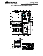
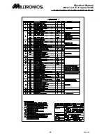
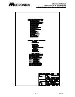
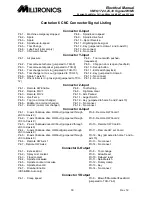
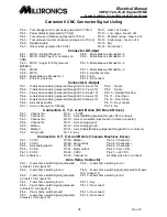
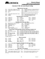
Centurion 6 CNC Connector Signal Listing
Connector X-Input
Pin 1 - Machine emergency stopped
Pin 8 - Spindle zero speed
Pin 2 - Spare
Pin 9 - Spindle drive fault
Pin 3 - Spare
Pin 10 – Spool Reverse
Pin 4 - Spindle up-to-speed
Pin 11 - Digitizing probe signal
Pin 5 - Tool Change
Pin 12 - Key (jumpered to Home-1 and X-axis10)
Pin 6 - Lube Fault (oiler empty)
Pin 13 - No connect
Pin 7 - CNC wait channel
Pin 14 - No connect
Connector Y-Input
Pin 1 - Air pressure
Pin 8 - Tool out switch pushed –
(requested)
Pin 2 - Tool carousel at home (jumpered to TCH-8)
Pin 9 - Chip pan door is open (feedhold)
Pin 3 - Tool carousel at pocket (jumpered to TCH-9)
Pin 10 - Set-up button
Pin 4 - Tool changer arm is in (jumpered to TCH-10)
Pin 11 - Edit switch (keylock)
Pin 5 - Tool changer arm is out (jumpered to TCH-11)
Pin 12 - Key (jumpered to Home-3
Pin 6 - Spare Y-axis 10)
Pin 13 - No connect
Pin 7 - Orient roller is in - prox signal (jumpered to TCH-
12)
Pin 14 - No connect
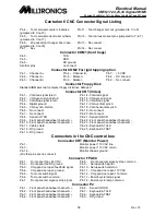
Connector Z-input
Pin 1 - Remote HW Enable
Pin 8 - Tool Setting
Pin 2 - Remote FOV1
Pin 9 - High/Low Gear
Pin 3 - Remote FOV2
Pin 10 - Arm Parked
Pin 4 - OverTemp
Pin 11 - Auger Switch
Pin 5 - Top (on arm tool changer)
Pin 12 - Key (jumpered to home 5 and Z-axis 10)
Pin 6 - Middle (on arm tool changer)
Pin 13 - No connect
Pin 7 - Bottom (on arm tool changer)
Pin 14 - No connect
Connector A-Input
Pin 1 - X-axis Yaskawa drive OK/Fault (jumpered through
JS3 to X-axis 9)
Pin 8 - Remote HW Coord 1
Pin 2 - Y-axis Yaskawa drive OK/Fault (jumpered through
JS3 to Y-axis 9)
Pin 9 - Remote HW Coord 2
Pin 3 - Z-axis Yaskawa drive OK/Fault (jumpered through
JS3 to Z-axis 9)
Pin 10 - Remote HW Coord 3
Pin 4 - A-axis Yaskawa drive OK/Fault(jumpered through
JS3 to A-axis 9)
Pin 11 – Remote HW set Coord
Pin 5 - B-axis Yaskawa drive OK/Fault (jumpered through
JS3 to B-axis 9)
Pin 12 - Key (jumpered to home 7 and A-
axis 10)
Pin 6 - Remote HW Axis 1
Pin 13 - No connect
Pin 7 - Remote HW Axis 2
Pin 14 - No connect
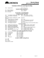
Connector X-Output
Pin 1 - Excess Error
Pin 8 - Tool change
Pin 2 - Spray mist coolant
Pin 9 - Allow Reset
Pin 3 - Flood coolant
Pin 10 - Delayed reset
Pin 4 - Spindle clockwise
Pin 11 - Spindle latch
Pin 5 - Spindle counter clockwise
Pin 12 - Rotary clamp
Pin 6 - Spindle drive OK
Pin 13 - Key
Pin 7 - Drawbar Enable
Pin 14 - No connect
(VK5 & MB-Auto only)
Connector Y-Output
Pin 1 - Creep speed
Pin 8 - Blowoff/Drumdoor/FeedHold
(jumpered to TCH-Yin9)


