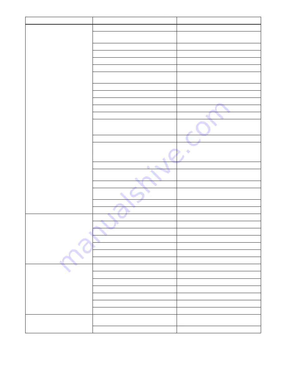
background image

OM-249474 Page 40

Trouble

Remedy

Probable Cause

Wandering, hunting or erratic arc.

Restriction in unspooler or drum adapter.

Replace unspooler or repair restriction.

Dirty or worn gun liner or inlet cable.

Remove gun liner or inlet cable and clean or 

replace.

Sharp bends or kinks in gun cable or liner.

Straighten gun cable and/or replace liner.

Loose or worn contact tip.

Tighten or replace contact tip.

Wrong size or type of contact tip.

Replace with proper size and type contact tip.

Gun overheating.

Use gun with proper amperage rating.

Loose power cables or other electrical 

connections.

Tighten, repair or replace connections or cables,

also check all rotary or brush type connections.

Incorrect gun or torch angle.

Set proper gun angle.

Too much or too little gas flow.

Adjust for proper gas flow.

Moisture in shielding gas.

Replace gas cylinder or supply.

Wrong gas for wire type or transfer mode.

Use correct shielding gas.

Wrong program selection for pulse welding.

Make proper program selection.

Improper or unsteady analog command from robot

controller.

Check signal from robot controller (as a trouble-

shooting aid go to power source control of voltage

and wire speed).

Gun or outlet cable leaking.

Repair or replace faulty parts.

Incorrect nozzle to work distance.

Set proper distance [3/8 in to 5/8 in (9.5 to 15.9 mm)

for short arc, 5/8 in to 1 in (15.9 to 25.4 mm) for

pulse welding, and 3/4 in to 1-1/4 in (19.1 to 31.8

mm) for spray welding].

Voltage sensing leads open or shorted.

Repair or replace voltage sense leads.

High frequency noise in the area

Be sure proper grounding methods are followed

when TIG or plasma equipment is used in the area.

Arc blow.

see Section 8-9.

Drive motor tachometer or motor cable open or

shorted.

Check drive motor tachometer and cables, and re-

pair or replace.

Wrong size drive rolls.

Replace with proper size drive rolls.

Too much or too little drive roll pressure.

Adjust drive roll pressure.

Welding wire burns back to contact tip at

the start of a weld.

Restriction in wire feed system.

Check inlet cable, gun liner and wire guides.

Worn drive rolls.

Replace drive rolls.

Wrong size drive rolls.

Replace with proper size drive rolls.

Improper start parameters.

Adjust start parameters.

Worn contact tip.

Replace contact tip.

Wrong size or type of contact tip.

Replace with proper size and type contact tip.

Not enough cast in welding wire.

Add a wire straightener to put cast in wire.

Welding wire burns back to contact tip

during welding.

Restriction in wire feed system.

Check inlet cable, gun liner and wire guides.

Worn drive rolls.

Replace drive rolls.

Wrong size drive rolls.

Replace with proper size drive rolls.

Too much or too little drive roll pressure.

Adjust drive roll pressure.

Worn contact tip.

Replace contact tip.

Wrong size or type of contact tip.

Replace with proper size and type contact tip.

Not enough cast in welding wire.

Add a wire straightener to put cast in wire.

Welding wire burns back to contact tip at

the end of a weld.

Welding power source output not shutting off.

Make sure all switches are in correct position, re-

pair power source if necessary.

Burnback setting too high or too long.

Adjust burnback setting or turn off completely.

Summary of Contents for 907439002

Page 1: ...Automatic Welding Interface And Arc Welding Power Source File Advanced Manufacturing Systems R Scan this tag with your mobile device to learn more about this product Individual carrier rates may apply...

Page 2: ...inue the tradition They re just as committed to providing equipment and service that meets the high standards of quality and value established in 1929 This Owner s Manual is designed to help you get t...

Page 3: ...s 13 4 3 Dimensions And Weight 13 4 4 Duty Cycle And Overheating 14 4 5 Volt Ampere Curves 14 4 6 Electrical Service Guide 15 4 7 Environmental Specifications 16 SECTION 5 SPECIFICATIONS FOR AXCESS E...

Page 4: ...2 9 1 Operational Terms 42 9 2 Pulse Welding Terms 43 9 3 Front Panel Switches 44 SECTION 10 MAINTENANCE 45 10 1 Routine Maintenance 45 10 2 Blowing Out Inside Of Unit 45 SECTION 11 TROUBLESHOOTING 47...

Page 5: ...9002 AXCESS E 300 CE 907440002 Council Directives 2014 35 EU Low Voltage 2014 30 EU Electromagnetic Compatibility 2011 65 EU Restriction of the use of certain Hazardous Substances in electrical and el...

Page 6: ...tings programs only valid until setting options welding programs are changed Occupational exposure is below the Exposure Limit Values ELVs YES NO for health effects at the standardized configurations...

Page 7: ...neeling or lying or when there is a high risk of unavoid able or accidental contact with the workpiece or ground For these conditions use the following equipment in order presented 1 a semiautomaticDC...

Page 8: ...ared according to AWS F4 1 and AWS A6 0 see Safety Standards D Do not weld where the atmosphere can contain flammable dust gas or liquid vapors such as gasoline D Connect work cable to the work as clo...

Page 9: ...S can injure D Keep away from moving parts such as fans D Keep all doors panels covers and guards closed and securely in place D Have only qualified persons remove doors panels covers or guards for ma...

Page 10: ...PA Standard 51B from National Fire Protection Association Quincy MA 02269 phone 1 800 344 3555 website www nfpa org OSHA Occupational Safety and Health Standards for General Indus try Title 29 Code of...

Page 11: ...s dans un environnement humideou si l on porte des v tements mouill s sur des structures m talliquestelles que sols grilles ou chafaudages en position coinc e comme assise genoux ou couch e ou s il y...

Page 12: ...br lures Le contact accidentel de l lectrode avec des objets m talliques peut provoquer des tincelles une explosion un sur chauffement ou un incendie Avant de commencer le soudage v rifier et s assur...

Page 13: ...areil D Tenir l quipement c bles et cordons distance des v hicules mobiles lors de toute op ration en hauteur D Suivre les consignes du Manuel des applications pour l quation de levage NIOSH r vis e P...

Page 14: ...ational Electrical Code NFPA Standard 70 from National Fire Protec tion Association Quincy MA 02269 phone 1 800 344 3555 website www nfpa org and www sparky org Safe Handling of Compressed Gases in Cy...

Page 15: ...ck by insulating yourself from work and ground Safe3 2012 05 Disconnect input plug or power before working on machine Safe5 2012 05 Keep your head out of the fumes Safe6 2012 05 Use forced ventilation...

Page 16: ...not use one eye bolt to lift or support unit Safe31 2012 05 Do not discard product with general waste Reuse or recycle Waste Electrical and Electronic Equipment WEEE by disposing at a designated coll...

Page 17: ...Symbols And Definitions Some symbols are found only on CE products A Amperage Direct Current DC Alternating Current AC V Voltage Output Circuit Breaker Remote On Off Positive Negative Voltage Input Ar...

Page 18: ...OM 249474 Page 12 Notes...

Page 19: ...Range Wire Feed Speed Range Wire Diameter Range Max Open Circuit Voltage DC Amperes Input At Rated Load Out put 50 60 Hz Three Phase Input kVA Input KW 400V Three Phase 225 A 25 V DC 100 Duty Cycle 10...

Page 20: ...void warranty Overheating 0 15 A V OR Reduce Duty Cycle Minutes duty1 4 95 230 226 B Continuous Welding 100 Duty Cycle At 225 Amperes 60 Duty Cycle At 300 Amperes 6 Minutes Welding 4 Minutes Resting...

Page 21: ...ctual input voltage should not exceed 10 of indicated required input voltage If actual input voltage is outside of this range output may not be available 50 60 Hz Three Phase Input Voltage V 400 Input...

Page 22: ...with the distribution network operator if necessary that the system impedance complies with the impedance restrictions ce emc 1 2014 07 C China EEP Hazardous Substance Information China EEP Hazardous...

Page 23: ...ire Feed Speed Range Wire Diameter Range Max Open Circuit Voltage DC Amperes Input At Rated Load Output 50 60 Three Phase Input kVA Input KW 400V Three Phase 400 V Input 450 A 36 5 V DC 100 Duty Cycle...

Page 24: ...arranty Overheating 0 15 A V OR Reduce Duty Cycle Minutes duty1 4 95 220 485 A Continuous Welding 100 Duty Cycle At 450 Amperes 60 Duty Cycle At 580 Amperes 6 Minutes Welding 4 Minutes Resting 5 5 Vol...

Page 25: ...Actual input voltage should not exceed 10 of indicated required input voltage If actual input voltage is outside of this range output may not be available 50 60 Hz Three Phase Input Voltage V 400 Inp...

Page 26: ...with the distribution network operator if necessary that the system impedance complies with the impedance restrictions ce emc 1 2014 07 C China EEP Hazardous Substance Information China EEP Hazardous...

Page 27: ...GENERAL INSTALLATION Appearance of actual unit may vary from unit shown in manual Special installation may be required where gaso line or volatile liquids are present see NEC Article 511 or CEC Secti...

Page 28: ...Workpiece 8 Voltage Sensing Lead Recommendedfor Accu pulse and required for RMD Positive voltage sensing lead is contained in the motor cable 9 Positive Weld Cable 7 2 Connection Diagram 1 2 3 4 5 7 8...

Page 29: ...Upper Rear Panel Receptacles 1 3 6 2 4 5 Ref 245 741 C 1 115 V 10 A AC Receptacle RC2 Receptacle supplies 60 Hz single phase power Maximum output from RC2 is limited by supplementary protector CB1 to...

Page 30: ...o weld B A short to socket A allows unit to weld The E Stop option comes with a 2 pin amphenol receptacle matching plug and 30 ft 9 m of high density molded cord to allow connecting the welding power...

Page 31: ...ero volts Measure input capacitor voltage on both inverter assemblies before proceeding If the capacitor voltage does not drop to near zero after several minutes use a bleeder resistor of between 25 a...

Page 32: ...Needed 5 16 in Route ground conductor through tubing and current transducer to ground terminal 3 8 1 5 9 7 10 11 L1 L2 L3 GND PE Earth Ground Input5 2016 06 251 184 C Ref 803 855 B Ref 803 766 C 219...

Page 33: ...strain relief Tighten strain relief S Use large strain relief for input conductor size 8 and larger S Use small strain relief with reducing wash ers for input conductor size 10 Connect input conducto...

Page 34: ...120 2x2 0 2x70 2x2 0 2x70 300 1 50 1 0 60 2 0 70 3 0 95 4 0 120 2x2 0 2x70 2x3 0 2x95 2x3 0 2x95 350 1 0 60 2 0 70 3 0 95 4 0 120 2x2 0 2x70 2x3 0 2x95 2x3 0 2x95 2x4 0 2x120 400 1 0 60 2 0 70 3 0 95...

Page 35: ...ircuit both positive and negative cables combined and maximum welding amperes See Section 8 2 to select proper cable size 1 Weld Output Terminal 2 Supplied Weld Output Terminal Nut 3 Weld Cable Termin...

Page 36: ...e with a standard welding circuit connection The length of a welding circuit is determinedas follows Welding Circuit Electrode Cable Length ECL Work Cable Length WCL Workpiece Length WL See Section 8...

Page 37: ...ally becomes enabled for all semi automatic processes The work sense lead connects to the Axcess welding power source 4 pin connector located above the negative output terminal This work sense lead au...

Page 38: ...elding gas regulator and shielding gas connection for each welding gun Arc blow is the deflection of a welding arc from its normal path due to magnetic forces It will adversely affect the appearanceof...

Page 39: ...gement is a bad setup due to sensing leads being directly in the current flow path of the welding arc Interaction between welding circuits will affect voltage drop in the workpiece The voltage drop ac...

Page 40: ...ing Lead 6 Wire Feeder 7 Workpiece This arrangement is a better setup for supporting separate voltage feedback to the welding power sources The most accurate voltage sensing may not be achieved due to...

Page 41: ...4 Work Cable 5 Voltage Sensing Lead 6 Wire Feeder 7 Workpiece This arrangement is the best setup for proper voltage sensing at the workpiece Voltage feedback to the welding power sources will more ac...

Page 42: ...ousing S Check gun connection at wire drive and be sure O rings seal at drive housing S Check condition of gas diffuser S Check condition of nozzle S Check O ring for proper sealing at nozzle Welding...

Page 43: ...und the arc a condition that normally exists when welding is performed near the end of ferromagneticmaterials Although arc blow cannot always be completely eliminated it can be controlled or reduced t...

Page 44: ...rive rolls Replace with proper size drive rolls Too much or too little drive roll pressure Adjust drive roll pressure Too much tension set at wire spool Reduce wire spool tension Restriction in unspoo...

Page 45: ...work distance Incorrect gun or torch angle Set proper gun angle porosity or dirty welds mean gun angle is too large Nozzle restriction Clean off spatter or remove restriction Breeze or drafts in weld...

Page 46: ...eplace voltage sense leads High frequency noise in the area Be sure proper grounding methods are followed when TIG or plasma equipment is used in the area Arc blow see Section 8 9 Drive motor tachomet...

Page 47: ...ize drive rolls improper drive roll pressure setting or wire not unspooling or restriction in drum adapter check wire feed system Shutdown at arc initiation using robot controller No arc detected Chec...

Page 48: ...ons Gas Type Selection of shielding gas being used in application IGNR Ignore Allows the use of a dual schedule switch between ignore welds and count welds when using Insight Centerpoint Inductance In...

Page 49: ...n WFS Term used to represent wire feed speed In MIG mode wire feed setting is independent of voltage setting In pulse and Accu pulse adjusting wire feed speed also increases power level on wire elec t...

Page 50: ...M 249474 Page 44 9 3 Front Panel Switches Ref 245 746 B 1 Power Switch Turns unit On or Off 2 Pilot Light Light indicates status of welding power source on when unit is on and off when unit is off 1 2...

Page 51: ...l Replace To be done by Factory Authorized Service Agent Reference Every 3 Months l Unreadable Labels Weld Terminals l Damaged Gas Hose nl Weld Cables nl Cords nl Gun Cables Every 6 Months OR Drive R...

Page 52: ...OM 249474 Page 46 Notes...

Page 53: ...ee Section 7 5 Wire does not feed Check supplementary protector CB2 and reset if necessary see Section 7 5 Check motor control cable connections Wire feeds erratically Readjust hub tension Readjust dr...

Page 54: ...Axcess power source is upgraded to an Axcess E the first time the unit is powered up the message CHCK WEB will appear on the display see Figure 11 1 Process Setup Adjust Feeder Setup V t A CHCK WEB 1...

Page 55: ...mation must be entered on the web pages for the unit to function properly The user will be prompted for power source serial number model and type Semi Auto AROI AUTO etc as shown in Figure 11 2 Figure...

Page 56: ...re compatible If these software versions are not compatible the ERR S W will appear on the display see Figure 11 3 Compatible software can be downloaded from www MillerWelds com Process Setup Adjust F...

Page 57: ...unit lo cated on the E Module Board Stack Refer to Section 11 5 for information on diagnostic LEDs Reinstall cover after checking diagnostic LEDs 250 237 A Ref 245 768 C 11 4 E Module Board Stack Diag...

Page 58: ...uxiliary not in use D19 AD AUX Flashing Indicates normal operation Off Indicates problem with AD micro D21 AD AWAKE On Indicates normal operation Off Indicates problem with AD micro B DeviceNet Power...

Page 59: ...rized Service Agent Off Indicates no error D33 On Contactor Indicates unit is receiving a contactor On signal Off Indicates contactor on signal is not being received Check input connections D43 On ARM...

Page 60: ...es Port A on the power source is factory set to 169 254 0 2 as a static IP address Connect a PC to Port A and enter 169 254 0 2 in the web browser to access the web pages AXCESS E Login Page ITW Weldi...

Page 61: ...ware System Settings Machine Lifetime Report Short Term Weld Data Weld Communications Errors Time Settings Ethernet Settings More Subselect and type additional text here Welder Information Subselect a...

Page 62: ...13 1 Circuit Diagram For Axcess E 300 CE 1 Of 2 57 Figure 13 2 Circuit Diagram For Axcess E 300 CE 2 Of 2 58 Figure 13 3 Circuit Diagram For Axcess E 450 CE 1 Of 2 60 Figure 13 4 Circuit Diagram For...

Page 63: ...Circuits OM 249474 Page 57 SECTION 13 ELECTRICAL DIAGRAMS 263 464 C Part 1 Of 2 Figure 13 1 Circuit Diagram For Axcess E 300 CE 1 Of 2...

Page 64: ...OM 249474 Page 58 Figure 13 2 Circuit Diagram For Axcess E 300 CE 2 Of 2...

Page 65: ...Circuits OM 249474 Page 59 263 464 C Part 2 Of 2...

Page 66: ...OM 249474 Page 60 Figure 13 3 Circuit Diagram For Axcess E 450 CE 1 Of 2...

Page 67: ...Circuits OM 249474 Page 61 263 483 C Part 1 Of 2...

Page 68: ...OM 249474 Page 62 Figure 13 4 Circuit Diagram For Axcess E 450 CE 2 Of 2...

Page 69: ...Circuits OM 249474 Page 63 263 483 C Part 2 Of 2...

Page 70: ...OM 249474 Page 64 Figure 13 5 Circuit Diagram For Axcess E Module...

Page 71: ...Circuits OM 249474 Page 65 250 571 C...

Page 72: ...ST FOR AXCESS E 300 Hardware is common and not available unless listed 249 544 F 6 Fig 14 4 7 Fig 14 2 8 Fig 14 5 24 Fig 14 6 3 Fig 14 3 1 2 2 4 5 9 9 11 11 12 14 13 13 15 16 17 18 19 20 21 22 23 10 F...

Page 73: ...1 13 219844 Label Warning Electric Shock Exploding Parts Wdles 2 14 219842 Label Warning Input Connections Electric Shock CE 1 15 213386 Assembly Filter Primary 1 16 HD2 182918 Transducer Current 400...

Page 74: ...er 1 9 196349 Spacer Windtunnel 3 10 T1 203408 Xfmr HF Litz Litz 1 11 Z1 220496 Output Inductor Assy 1 12 170647 Bushing Snap in Nyl 1 312 Id X 1 500 Mtg Hole 2 13 179276 Bushing Snap in Nyl 1 000 Id...

Page 75: ...4 Cable Transducer 20in 1 29 R1 R2 196343 Resistors W Leads Plug 1 196840 Insulator Resistors Interface Board 1 30 109056 Core Ferrite E 2 164 Lg X 1 094 High X 826 Wide 1 31 L2 196345 Coil Inductor P...

Page 76: ...ss E 1 8 246591 Ground Strap 2 9 222808 Insulator 1 10 245350 Assembly Personality Board 1 11 240728 Nameplate Axcess E Top Front 1 12 244237 Dust Cap 1 13 244239 Cable USB Type A Sealed Panel Mount 1...

Page 77: ...rcuit card Aux Power 1 3 170647 Bushing Snap in Nyl 1 312 Id X 1 500 Mtg Hole 1 4 210491 Panel Mtg Components Top 1 5 083147 Grommet SCR No 8 10 Panel Hole 312 Sq 500 High 4 Recommended Spare Parts Wh...

Page 78: ...eset 1P 15A 250VAC Frict 1 8 RC2 196814 Receptacle w Leads 115V Duplex 1 9 PC12 239623 Circuit Card Assy E Stop 1 10 115440 Stand off no 6 32 x 687 lg 250 hex al fem 4 11 212764 Plug Assy Rear 1 E sto...

Page 79: ...980 Bus Bar Output 1 6 244989 Circuit Card Assy Vsense Filter 1 7 210866 Terminal Pwr Output Black 1 8 248552 Panel Front 1 9 219843 Label Work Sense 1 10 207979 Box Louver 1 11 186621 Boot Generic 2...

Page 80: ...AXCESS E 450 Hardware is common and not available unless listed 249 528 F 1 26 Fig 15 6 6 Fig 15 4 7 Fig 15 2 10 Fig 15 5 3 Fig 15 3 2 2 4 5 8 9 11 11 13 13 14 16 15 15 17 18 19 20 21 22 23 24 25 7 1...

Page 81: ...al Precautionary Wordless Intl Small 2 14 210482 Base 1 15 219844 Label Warning Electric Shock Exploding Parts Wdles 2 16 219842 Label Warning Input Connections Electric Shock CE 1 17 213386 Filter As...

Page 82: ...er 1 9 196349 Spacer Windtunnel 3 10 T1 203408 Xfmr HF Litz Litz 1 11 Z1 220496 Output Inductor Assy 1 12 170647 Bushing Snap in Nyl 1 312 Id X 1 500 Mtg Hole 2 13 179276 Bushing Snap in Nyl 1 000 Id...

Page 83: ...15v 1 196384 Cable Transducer 20in 1 29 R1 R2 196343 Resistors W Leads Plug 1 196840 Insulator Resistors Interface Board 1 30 109056 Core Ferrite E 2 164 Lg X 1 094 High X 826 Wide 1 31 L2 196345 Coi...

Page 84: ...ss E 1 8 246591 Ground Strap 2 9 222808 Insulator 1 10 245350 Assembly Personality Board 1 11 240728 Nameplate Axcess E Top Front 1 12 244237 Dust Cap 1 13 244239 Cable USB Type A Sealed Panel Mount 1...

Page 85: ...Aux Power 1 3 170647 Bushing Snap in Nyl 1 312 Id X 1 500 Mtg Hole 1 4 210491 Panel Mtg Components Top 1 5 083147 Grommet SCR No 8 10 Panel Hole 312 Sq 500 High 4 Recommended Spare Parts When orderin...

Page 86: ...Reset 1P 15A 250VAC Frict 1 8 RC2 196814 Receptacle w Leads 115V Duplex 1 9 PC12 239623 Circuit Card Assy E Stop 1 10 115440 Stand off no 6 32 x 687 lg 250 hex al fem 4 11 212764 Plug Assy Rear 1 E S...

Page 87: ...Thd 2 6 PC15 PC20 244993 Circuit Card Assy Stud Filter 2 7 207897 Bus Bar Output 2 8 210866 Terminal Pwr Output Black 1 9 247005 Panel Front 1 10 219843 Label Volt Sense 1 11 207896 Box Louver 1 12 1...

Page 88: ...auge 063 in 22 Gauge 031 in 24 Gauge 025 in 20 Gauge 037 in 18 Gauge 050 in 14 Gauge 078 in 1 8 in 125 in 3 16 in 188 in 1 4 in 25 in 5 16 in 313 in 3 8 in 375 in 1 2 in 5 in MATERIAL THICKNESS REFERE...

Page 89: ...ns and Subarc SAW Torches Remote Controls and RFCS RJ45 Replacement Parts No labor Roughneck Guns Spoolmate Spoolguns Miller s True Blue Limited Warranty shall not apply to 1 Consumable components suc...

Page 90: ...your personal records Always provide Model Name and Serial Style Number Contact a DISTRIBUTOR or SERVICE AGENCY near you Welding Supplies and Consumables Options and Accessories Personal Safety Equip...

Reviews: