


26
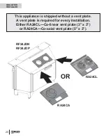
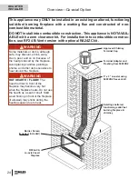
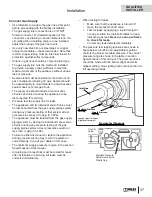
Dimensions—Co-linear Option
17-3/4”
23”
14”
26-1/2”
1-3/4”
1-1/8”
18-3/4”
15-7/8”
20-1/8”
19”
14” - to screen
14-5/8” - to brackets
15-3/4” - w/fret
14”
(Baffle extends to 18”)
8-1/4”
7-1/2”
Gas Inlet
3/8” NPT
Female
Centerline
Gas Inlet
3/8” NPT Female
Control
Valve
Location
Optional Fret:
Mounting
Brackets
Optional Fan
Speed Control
Location
(this side at front)
Control Valve
Optional
Cast Fret
Maintain a
3/4” gap in
front of
barrier
screen
Barrier
Screen
Adjustable
Convection
Baffle
Front Face of
Barrier Screen
Levelling
Feet
Side View
Front View
Top View
1-3/8”
4-1/2”
26”
Window Cover & Barrier Screen
4-3/16”
Minimum Cavity Dimensions
The diagram shows minimum dimensions required to install
the RF24. Cavities having a combination of all the minimum
dimensions shown possible, may prove to be diffi cult
installations.
24-1/2”
8”
25-1/2”
27”
10”
11”
RA24TB Fret (Black)
1225VFB Ventana Fret (Black)
RA24CV Fret (Vintage Iron)
RA24AV Fret (Vintage Iron)
Optional Frets
24-3/8”
7-5/8”
18”
18”
20”
27”
Height to Smoke Curtain
Minimum Insert Cavity
14” without fret
15-3/4” with fret
Important:
A free space of 3/4 inch (19 mm) is required in front
of the barrier screen to allow the window to move and relieve
during a hard start. The use of the optional fret sets this space
with the fret bracket installed.
However, when the fret is not used and the bottom cover is
used instead, this space immediately in front of the barrier
screen must be added to the minimum depth as a safety
precaution.
It is very important to ensure that the area
immediately in front of the barrier screen is kept clear at all
times even when not using a fret.
QUALIFIED
INSTALLER


