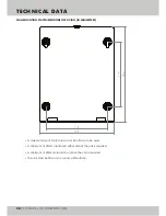
TECHNICAL DATA
06
TECHNICAL DOCUMENTATION
CONNECTION TO THE SYSTEM
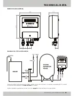
The Mikrofill 3 is connected to the system by way of the 15mm outlet isolation valve. The pipework from the unit
should be made in 15mm copper or similarly approved plastic pipework. A suitable sized expansion vessel
should be incorporated into the system at this point (please refer to the typical installation diagram on
page
07
for more information).
Please contact our technical department on
03452 60 60 20
if you require any assistance regarding vessel
sizing.
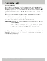
The final connection into the system should be sized accordingly, recommendations are shown below:
• Vessel size up to
½”
• Vessel size up to
¾”
• Vessel size up to
1”
For vessel sizes in excess of 1000L capacity please contact our technical department.
IMPORTANT NOTE:
DRAIN
Following every fill procedure the unit will discharge a small amount of water, establishing an air break. For this,
the unit is supplied fitted with a ¾” BSP tundish, which must be connected to a suitable drain.
Mikrofill Systems Ltd. cannot accept responsibility for any consequential damage caused by failure to
connect the tundish to a suitable drain.
100L:
300L:
1000L:
(15mm) expansion pipework
(22mm) expansion pipework
(28mm) expansion pipework
The expansion vessel air / nitrogen charge must be set to the same pressure as the cold fill
pressure of the system.
If the installed height of the expansion vessel is different to that of the unit then please
contact our technical department who will advise on the air / nitrogen charge required.
A suitably sized pressure relief / safety valve
MUST
be fitted on all sealed systems.
Summary of Contents for 3
Page 2: ......


