MAINTENANCE
16
TECHNICAL DOCUMENTATION
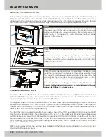
REMOVING THE CONTROLS ASSEMBLY
In the unlikely event of either a sensor or PCB failure, it may be necessary to replace the controls assembly. If
this is the case then the unit must first be isolated mechanically and electrically, and then drained down by
slackening the top inlet and system valve nuts, allowing any water in the internal pipework of the unit to drain
out. Once this is done, the controls assembly may be removed by following the steps listed below.
CLEANING THE SOLENOID VALVES
Over time either or both solenoid valves inside the unit can become blocked up with limescale or debris and
this can affect their operation. The most common indication that a solenoid valve is blocked is a steady flow
of water constantly passing through the unit and out to drain.
To diagnose which of the two solenoid valves is blocked, when the unit is still passing to drain it should be
powered off completely. If the unit continues to pass then the normally closed solenoid valve in the top left of
the unit will require cleaning. If the unit stops passing when powered off then the normally open solenoid valve
directly above the tundish will require cleaning.
To clean the solenoid valve(s) and stop them passing, the unit must first be isolated and disconnected both
mechanically and electrically. The wiring cover at the bottom of the unit is held in position by a single screw
which can be removed with a PZ2 screwdriver to give access to the terminal block where the unit can then
be disconnected electrically. Once fully isolated and disconnected both mechanically and electrically, the
unit can be removed from the wall by unscrewing the slot-head bolt on the topside of the unit and lifting then
pulling the unit from its backplate.
With the unit removed from the wall, the steps detailed on the following page will explain how to access and
clean out both solenoid valves.
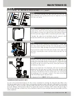
Unscrew the two retaining screws on either side of the front of the
controls housing until they are extended enough to be able to grip and
pull the control assembly forward and clear of the unit, ensuring not to
pull it too far as to damage the wiring still connecting the controls
assembly to the main unit.
Unclip the two push-fit connectors holding the sensors to the pipework
fittings.
This is done by depressing the orange retaining clip on the push-fit
connector inwards and then pulling the connector and sensor away
from the pipework fitting, which should be clipped into a slot in the front
casing to hold it in place.
With both sensors disconnected from the pipe fittings, the ribbon cable
should then be removed from the back of the controls assembly. Once
this is done, the controls assembly will be completely detached from the
main unit and the above steps should be reversed in order to refit or
replace the controls assembly back into the Mikrofill 3.
Care should be taken when fixing a controls assembly into the main unit
to ensure that the two retaining screws are not over-tightened as this can
damage the PCB and / or plastic casings.
STEP 01:
STEP 02:
STEP 03:
Summary of Contents for 3
Page 2: ......


