background image

All images shown in the manual are for illustration purpose only.

Introduction


Introduction  

4

It's good to know   

6

Power supply unit


Power supply 

7

How to power the board? 


8

Supported MCUs


Default MCU Card 

9

How to properly place your MCU into the DIP socket? 

11

Other supported MCU cards 

12

Programmer/debugger


On-board programmer  

13

Connectivity


INPUT/OUTPUT group 

15

Headers, buttons, LEDs 

16

mikroBUS

 sockets 

17

Click boards

™ 

18

Communication


USB UART A  

20

USB UART B 

21

USB host 

22

USB device 

23

Ethernet 24
CAN 25
 

Multimedia


Audio I/O 

26

microSD card slot 

27

TFT display 

28

Touch panel controller 

29 

GLCD 128x64 

30

Navigation switch 

31

Other modules


DS1820 Digital temp. sensor 

32

LM35 Analog temp. sensor 

33

Serial Flash Memory 


34

I2C EEPROM 

35

ADC INPUTS 

36

Piezo buzzer 

37

Additional GNDs 

338


Table of contents


Summary of Contents for EasyMx PRO v7a

Page 1: ...U S E R M A N U A L mikroBUS SOCKETS CODEGRIP ON BOARD MCUs SUPPORTED 857 MULTIMEDIA PERIPHERALS AMAZING CONNECTIVITY ...

Page 2: ...as born And we all grew together with EasyMX In its each and tiniest piece we had put all of our energy creativity and sense of what s the best for an engineer I ve personally assembled hundreds of early EasyMx boards myself with my home soldering iron Today in 2022 we present you the A generation of the board which brings us some awesome new features We hope that you will like it as much as the p...

Page 3: ...ger On board programmer 13 Connectivity INPUT OUTPUT group 15 Headers buttons LEDs 16 mikroBUS sockets 17 Click boards 18 Communication USB UART A 20 USB UART B 21 USB host 22 USB device 23 Ethernet 24 CAN 25 Multimedia Audio I O 26 microSD card slot 27 TFT display 28 Touch panel controller 29 GLCD 128x64 30 Navigation switch 31 Other modules DS1820 Digital temp sensor 32 LM35 Analog temp sensor 3...

Page 4: ...are EasyMx PRO v7a is all about connectivity Having two different connectors for each port you can connect accessory boards sensors and your custom electronics easier then ever before Powerful on board CODEGRIP USB C programmer and In Circuit debugger can program and debug over 850 microcontrollers You will need it whether you are a professional or a beginner 2 CONNECTORS FOR EACH PORT EVERYTHING ...

Page 5: ......

Page 6: ... x 220 mm 10 47 x 8 66 inch BOARD WEIGHT 500g 1 1 lbs 1 2 3 STM32F207VGT6 belongs to ARM Cortex M3 family It has 120MHz frequency 1 Mbyte of Flash memory 128K 4K bytes of general purpose SRAM integrated Ethernet controller USB 2 0 OTG Host Device 83 General purpose I O pins 12x16 bit and 2x32 bit timers 3x12 bit A D 24 channels 2x12 bit D A 4xUSARTs 2xUARTs internal Real time clock RTC 2xI2C 3xSPI...

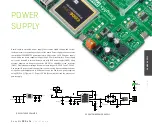
Page 7: ...ernal adapter voltage levels must be in range of 9 32V DC and 7 23V AC Use jumper J9 to specify which power source you are using Upon providing the power using either external adapters or USB power source you can turn on power supply by using SWITCH 1 Figure 3 1 Power LED ON Green will indicate the presence of power supply J9C D3 1N4007 D4 1N4007 D5 1N4007 D6 1N4007 CN30 CN31 VCC 5V POWER R68 2K2 ...

Page 8: ...oard power supply creates stable 3 3V necessary for operation of the microcontroller and all on board modules To power the board with USB cable place jumper J9 in USB position You can then plug in the USB cable as shown on images and turn the power switch ON To power the board via adapter connector place jumper J9 in EXT position You can then plug in the adapter cable as shown on images and turn t...

Page 9: ... 3xSPI and 2xCAN controllers 25MHz crystal oscillator We carefully chose the most convenient crystal value that provides clock frequency which can be used directly or with the PLL multipliers to create higher MCU clock value MCU card also contains 32 768 kHz crystal oscillator which provides external clock for RTC module USB communications lines These two jumpers when in USB position connect D and...

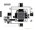
Page 10: ... 2 3 4 5 6 7 11 12 8 1 9 10 VDD2A LED1 LED2 XTAL2 XTAL1 VDDCR RXD1 RXD0 VDDIO RXER CRS_DV MDIO MDC nINT RST TXEN TXD0 TXD1 TXP RXP Rbias RXN TXN VDD1A LAN8720A GND TXP TXN RXP RXN R2 12 1K FP1 VCC LED1 LED2 LED1 LED2 TXD1 TXD0 TXEN RST PB14_nINT RXD1 RXD0 CRS_DV TXD1 TXD0 TXEN PC1_MDC RXD1 RXD0 PB10_RXER CRS_DV PA2_MDIO C13 100nF C12 2 2uF R3 1 5K VCC R4 27 R5 27 R6 27 R7 27 R8 27 R9 27 PC4 PC5 PB...

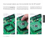
Page 11: ...troller slowly down until all the pins match the socket as shown on the second image Check again if everything is placed correctly and press the microcontroller until it is completely plugged into the socket as shown on the third image If done correctly all pins should be fully inserted Only now can you turn on the power supply How to properly place your microcontroller into the DIP socket Place b...

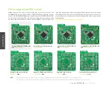
Page 12: ...nd one with Cortex M7 STM32F746VGT6 MCU You can also purchase empty PCB cards that you can populate on your own and solder any supported microcontroller you need in your development There are total of four empty PCB cards available This way your EasyMx PRO v7a board becomes truly flexible and reliable tool for almost any of your ARM projects MCU cards can also be used in your final devices For com...

Page 13: ...nally used USB Type A B connectors EasyMx PRO v7a development board is supported by a powerful CODEGRIP Suite offering complete control over the development board It is used to intelligently manage programming and debugging tasks and to configure various other options and settings providing visual feedback through its clean and comprehensive Graphical User Interface GUI Tobetterunderstandhowtooperat...

Page 14: ...BU1 A8 DN1 A7 DP1 A6 GND A1B12 VBUS A4B9 CC1 A5 CN20 USB TYPE C R94 5k1 R95 5k1 VCC USB D12 R105 27 L2 2 2µH C62 33 uF C61 220µF USB 5V C60 1u USB 5V USB PROG_N USB PROG_P R2 2K2 LD68 R96 6K8 LD80 R97 4K7 LD79 LINK ACTIVE DATA VCC 3 3V NRST PA13 MCU PB3 PA15 PA14 PA13 PB3 MCU PA15 MCU PA14 MCU CODEGRIP on board programmer schematic ...

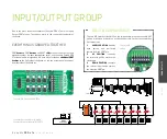
Page 15: ...res of EasyMx PRO v7a are it s Input Output PORT groups They add so much to the connectivity potential of the board EVERYTHING IS GROUPED TOGETHER PORT headers PORT buttons and PORT LEDs are next to each other and grouped together It makes development easier and the entire EasyMx PRO v7a cleaner and well organized We have also provided an additional PORT headers on the right side of the board so y...

Page 16: ...riate microcontroller pin The same goes for GND If DIP switch is in the middle position neither of two logic states will be applied to the appropriate microcontroller pin You can disable pin protection 220ohm resistors by placing jumpers J6 and J7 which will connect your push buttons directly to VCC or GND Be aware that doing so you may accidentally damage MCU in case of wrong usage LED Light Emit...

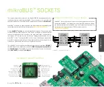
Page 17: ...ion interfaces SPI UART and I2 C There are also single pins reserved for PWM Interrupt Analog input Reset and SPI Chip Select The mikroBUS socket also contains pins with the two power rails 3 3V and 5V along with the GND pins R90 1K VCC 3 3V VCC 5V AN RST CS SCK MISO MOSI 3 3V GND PWM INT RX TX SCL SDA 5V GND 1 R91 1K VCC 3 3V VCC 5V AN RST CS SCK MISO MOSI 3 3V GND PWM INT RX TX SCL SDA 5V GND 2 ...

Page 18: ...ormances for the used components they save developers of testing and troubleshooting often associated with the prototyping phase They enhance rapid development and accelerate time to market These ready to use boards require no additional hardware configuration More information at www mikroe com click CODE EXAMPLES It s easy to get your Click board up and running We provided the examples for mikroC...

Page 19: ......

Page 20: ...ocontroller UART module To establish this connection you must connect RX and TX lines of the microcontroller to the appropriate input and output pins of the FT232RL This selection is done using DIP switches SW12 1 and SW12 2 1 2 3 4 5 6 7 8 9 10 11 12 13 14 15 16 17 18 19 20 21 22 23 24 25 26 27 28 TXD DTR RTS VCCIO RXD RI GND NC DSR DCD CTS CBUS4 CBUS2 CBUS3 CBUS0 CBUS1 OSCO OSCI TEST AGND NC GND...

Page 21: ... GND In order to enable USB UART B communication you must push SW12 3 PD5 and SW12 4 PD6 to ON position This connects the TX and RX lines to PD5 and PD6 microcontroller pins and its UART module If you need to use more than one USB UART in your application you have another USB UARTB connector available on the board too Both available USB UART modules can operate at the same time because they are ro...

Page 22: ...B1A12 VBUS B4A9 CC2 B5 DP2 B6 DN2 B7 SBU2 B8 SBU1 A8 DN1 A7 DP1 A6 GND A1B12 VBUS A4B9 CC1 A5 CN24 USB TYPE C R91 56k R90 56k VBUS4 USB is the acronym for Universal Serial Bus This is a very popular industry standard that defines cables connectors and protocols used for communication and power supply between computers and other devices EasyMx PRO v7a for contains USB HOST connector CN24 for USB St...

Page 23: ...2 5 1k R93 5 1k VBUS5 USB D_N USB D_P D_N D_P USB VBUS EasyMx PRO v7a for also contains USB DEVICE connector CN26 which enables microcontrollers that support USB communication to establish a connection with the target host eg PC Laptop etc It lets you build a slave USB device HID Composite Generic etc Connector supports USB Standard Type C plug Detection whether USB device is connected to HOST can...

Page 24: ...devices All four Ethernet lines TPOUT TPOUT TPIN andTPIN arerouteddirectlytothe MCU card socket and cannot be accessed via PORT headers Additional signalization LEDs green and yellow are provided on the Board next to RJ 45 connector Ethernet communication 1 3 5 7 9 11 13 15 17 19 21 23 25 2 4 6 8 10 12 14 16 18 20 22 24 26 MCU CARD SOCKET TX_P TX_N RX_P RX_N LED1 LED2 TD CT TD RD RD CT A2 A1 K1 K2...

Page 25: ... Transceiver and a pair of screw terminals which provide microcontrollers with integrated CAN controller with the necessary physical interface for CAN communication Make sure to correctly connect negative and positive differential communication lines before using this module VCC 3 3V R57 10 CN28 CANH CANL TX CAN RX CAN 1 2 3 5 4 6 7 8 D GND Vdd R Vref CANL CANH Rs U7 SN65HVD230 1 2 3 4 5 6 7 8 O N...

Page 26: ...S 23 GND4 22 GND3 21 TALI 18 TALO 17 GND1 16 CO 15 DRE 8 MCP LN 1 OVDD2 19 GPIO 9 GPIO 10 27 26 GND2 20 28 29 30 31 33 34 35 36 AGND 37 AVDD 38 RIGH 39 AGND 40 AGND 41 GBU 42 AVDD 43 RCA 44 AVDD 45 LEF 46 AGND 47 LN 48 MCP LN1 MICN XRESET DGND0 CVDD0 IOVDD0 CVDD1 DREQ GPIO2 GPIO3 GPIO6 GPIO7 XDCS BSYNC IOVDD1 VC0 DGND1 XTAL0 XTAL1 IOVDD2 DGND2 DGND3 DGND4 XCS CVDD2 GPIO5 RX TX SCLK SI SO XTEST GPI...

Page 27: ...ecial ferrite is also provided to compensate the voltage and current glitch that can occur when pushing in and pushing out microSD card into the socket Enabling microSD In order to access microSD card you must enable SPI communication lines using SW13 1 SW13 3 DIP switches as well as Chip Select CS and Card Detect CD lines using SW14 3 and SW14 4 switches microSD card slot FP2 FERRITE E13 10uF VCC...

Page 28: ...ard mode can also be driven with PWM signal in order to regulate brightness in 0 to 100 range TFT display 320x240 pixels TFT display is enabled using SW11 3 and SW11 4 DIP switches Back light can be enabled in two different ways 1 It can be turnedonwithfullbrightness using SW11 3 switch 2 Brightness level can be determined with PWM signal from the microcontroller allowing you to write custom back ...

Page 29: ...D PMWR GND VCC NC RS NC D1 D2 D3 D4 D5 D6 D7 CS D0 RST NC 5V BPWM 1 20 XR YU XL YD 21 24 GLCD TFT SOCKET Q3 BC856 Q4 BC846 R61 10K R59 1K VREF R65 10K R63 4K7 VCC 3 3V Q6 BC856 VREF R67 10K Q7 BC846 R71 10K C35 10nF R70 100K Q8 BC846 R78 10K C40 10nF R77 100K R75 4K7 VCC 3 3V RIGHT TOP DRIVEA DRIVEB E14 10uF VCC 3 3V FP4 FERRITE E15 10uF VCC 1 8V VREF LEFT BOTTOM PB8 PB9 1 2 3 4 5 6 7 8 O N SW11 D...

Page 30: ...play You can control the display contrast using dedicated potentiometer P2 Full brightness display back light can be enabled with SW11 3 switch and PWM driven back light with SW11 4 switch MULTIMEDIA VCC 5V BCK_LIGHT BCK_PWM PE9 GLCD_VEE VCC 5V VEE PE0 PE1 PE2 PE3 PE4 PE5 PE6 PE7 PE8 PE10 PE11 PE12 PE13 BCK_LIGHT BPWM PE15 CN32 GLCD TFT SOCKET Q5 BC846 R62 20 R66 4K7 R64 1K BCK_PWM BPWM VCC 3 3V P...

Page 31: ...r pins PD4 PB5 PD2 PA6 PC13 respectively Before using the navigation switch it is necessary to pull up mentioned microcontroller pins using tri state DIP switches located in I O groups After pressing the navigation switch in desired direction associated microcontroller pins are connected to GND which can be detected in user software Navigation switch 4 5 6 1 2 3 KEY1 UP LEFT CENTER RIGHT DOWN PD2 ...

Page 32: ...identify all devices sharing the same interface Board provides a separate socket TS1 for the DS1820 Communication line with the microcontroller is established using SW14 5 or SW14 6 DIP switch ON position Enabling DS1820 sensor MO DULES DS1820 connected to PB10 pin schematic DS1820 DIGITAL TEMP SENSOR EasyMx PRO v7a for STM32 enables you to establish 1 wire communication between DS1820 and the mic...

Page 33: ...nge from 2ºC to 150ºC Board provides a separate socket TS2 for the LM35 sensor in TO 92 plastic packaging Readings are done with microcontroller using single analog input line which is selected with DIP switch SW14 Switch connects the sensor with PC0 microcontroller pin EasyMx PRO v7a for STM32 enables you to get analog readings from the LM35 sensor using PC0 microcontroller pin The connection is ...

Page 34: ...ch are very popular today EasyMx PRO v7a features M25P80 Serial Flash Memory which uses SPI communication interface and has 8 Mbits of available memory organized as 16 sectors each containing 256 pages Each page is 256 bytes wide Thus the whole memory can be viewed as consisting of 4096 pages or 1 048 576 bytes Maximum clock frequency for READ instructions is 40MHz In order to connect Serial Flash...

Page 35: ...bus that is used to attach low speed peripherals to computer or embedded systems I C uses only two open drain lines Serial Data Line SDA and Serial Clock SCL pulled up with resistors WHAT IS I2C SCL line is driven by a master while SDA is used as bidirectional line either by master or slave device Up to 112 slave devices can be connected to the same bus Each slave must have a unique address In ord...

Page 36: ... is resolution Resolutionrepresentsthenumberofdiscretestepsthatsupportedvoltagerange canbedividedinto ItdeterminesthesensitivityoftheA Dconverter Resolutionisrepresented in maximum number of bits that resulting number occupies Most microcontrollers have 10 bit resolution meaning that maximum value of conversion can be represented with 10 bits which converted to integer is 210 1024 This means that ...

Page 37: ...rom 0 to 100 of the duty cycle You can generate PWM signal using hardware capture compare module which is usually available in most microcontrollers or by writing a custom software which emulates the desired signal waveform Piezo buzzer s resonant frequency where you can expect it s best performance is 3 8kHz but you can also use it to create sound in the range between 2kHz and 4kHz SUPPORTED SOUN...

Page 38: ... to easily connect oscilloscope GND reference when you monitor signals on microcontroller pins or signals of on board modules 1 2 3 GND pin located near the 4 digit 7 seg display GND pin located near the DIP28 socket and PORTD GND pin located near the DIP8 and DIP18B socket 3 oscilloscope GND pins are conveniently positioned so each part of the board can be reached with an oscilloscope probe ...

Page 39: ...own code please visit the Libstock website With user profiles you can get to know other programmers and subscribe to receive notifications on their code www libstock mikroe com Once you have chosen your compiler and since you already got the board you are ready to start writing your first projects We have equipped our compilers with dozens of examples that demonstrate the use of each and every fea...

Page 40: ... even if MikroElektronika has been advised of the possibility of such damages MikroElektronika reserves the right to change information contained in this manual at any time without prior notice if necessary TRADEMARKS The MikroElektronika name and logo the MikroElektronika logo mikroC mikroBasic mikroPascal mikroProg mikromedia EasyPIC Click boards and mikroBUS are trademarks of MikroElektronika A...

Page 41: ...kroe com If you are experiencing some problems with any of our products or just need additional information please place your ticket at www mikroe com support If you have any questions comments or business proposals please contact us at office mikroe com Time saving embedded tools ...

Reviews: