15
Important!
In order to avoid damage to plugs
and cables, good electric contact is
required when connecting the work
return cable and welding torch to
the machine.
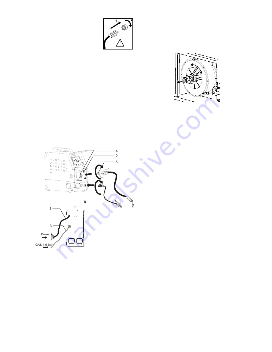
Connection of shielding gas
The shielding gas hose is fitted to the back panel of
the power source (3) and is connected to a gas supply
with a pressure reduction to 2-6 bar. One gas cylinder
can be mounted on the bottle carrier on the back of a
trolley if any.
Connection of torch for MIG/MAG welding
The welding hose assembly is pushed into the central
connector coupling (4) and the nut (5) is tightened by
hand. The return lead is connected to the negative
pole (6).
Torch adjustment (Dialog torch)
The current size can be adjusted both from the
machine and the welding torch if a welding hose with
dialog torch is in use. This function cannot be
disconnected. The torch adjustment is passive without
Dialog torch.
Inching
The function is used for wire inching e.g. after change
of wire. Wire inching starts by pressing the green key
pad and simultaneously triggering the torch trigger.
Wire inching continues even though the green key pad
has been released. It does not stop until the torch
trigger has been released again.
Adjustment of wire brake
The wire brake must ensure that the wire reel brakes
sufficiently quickly when welding stops. The required
brake force is depending on the weight of the wire reel
and the maximum wire feed speed. A brake torque of
1.5-2.0 Nm will be satisfactory for most applications.
Adjustment:
-
Dismount the control knob by placing a thin screw
driver behind the knob and thereafter pull it out
-
Adjust the wire brake by fastening or loosening the
self-locking nut on the axle of the wire hub
- Remount the knob by pressing it back into the
groove.
Summary of Contents for AUTOMIG 273i
Page 4: ......
Page 70: ...70 ...
Page 76: ...76 TRÅDFREMFØRING WIRE FEED UNIT DRAHTVORSCHUBEINHEIT DISPOSITIF DE GUIDAGE DE FIL ...
Page 78: ...78 ...
Page 79: ... ...


