


www.midtronicseurope.com
7 – Maintenance & Troubleshooting
EBT-965P
21
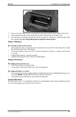
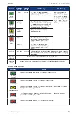
the other probe tip into the “teeth” pin hole. Wiggle the battery test cables. The resistance
reading should be less than 11 Ω.
Contacts for Cable Connector
Orientation of arrow
on cable connector
BLACK clamp,
NO teeth
RED clamp,
NO teeth
RED clamp,
TEETH
BLACK clamp,
TEETH
Contacts for Small Clamp
Contact point for
testing at “NO TEETH”
Contact point for
testing at “TEETH”
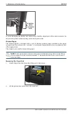
Connecting The Battery Test Cable
To prevent damage to the analyzer’s circuitry, do not
connect the analyzer to a voltage source greater than
30 Vdc.
To connect the battery test cable to the analyzer align the arrow on the cable connector with the
arrows on the analyzer’s housing. Hold the part of the cable connector as shown and firmly insert
the connector into analyzer’s six-pin receptacle. Do not twist.
Summary of Contents for EBT-965P
Page 2: ...blank page behind cover ...


