


Page 12
midlandusa.com
Model MXT500
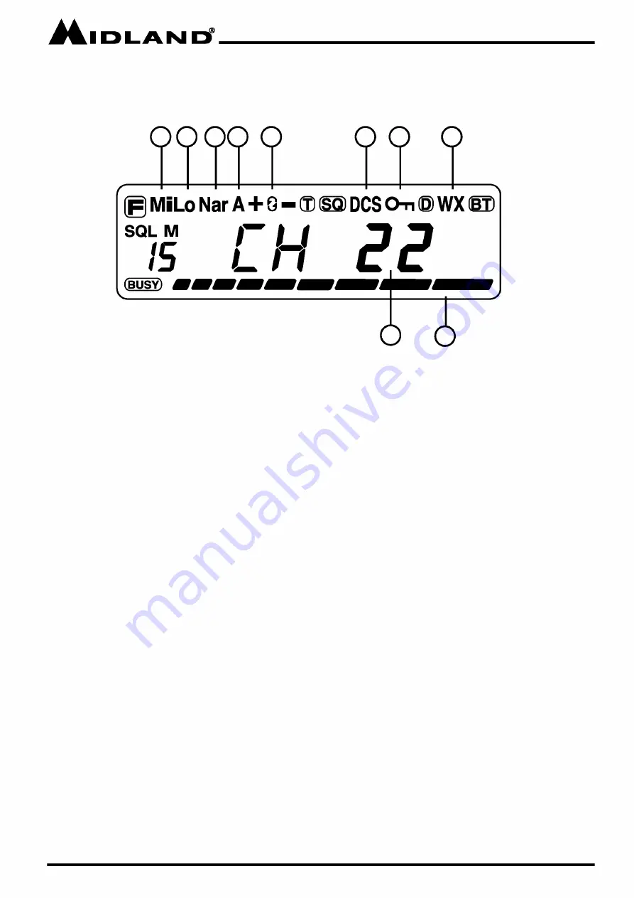
LCD DISPLAY
2. Medium Power
3. Low Power
4. Narrow Band Channel
5. Auto power off
6. Repeater offset direction
7. Scan Indicator
8. CTCSS Privacy Tone
9. DCS Privacy Tone
10. Key Lock
11. Weather band
12. Channel Icon
13. Menu item indicator
14. Receive indicator
15. Receive and transmit signal strength
12
13
2
3
4
5
7
9
10
11
Summary of Contents for MICRO MOBILE MXT500
Page 1: ......


