-i
V6-i VRF 50/60Hz
31
P
art
2
- Compo
nent
La
you
t and
R
ef
rig
e
ran
t C
ir
cu
its
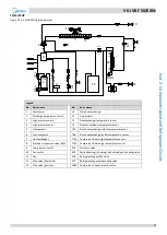
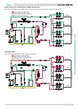
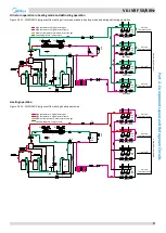
Oil return operation in heating mode and defrosting operation
Figure 2-3.19: 30/32HP refrigerant flow during oil return operation in heating mode and during defrosting operation
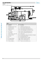
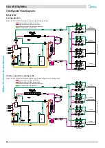
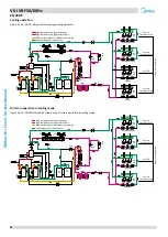
Heating operation
Figure 2-3.20: 30/32HP refrigerant flow during heating operation
480 steps
Filter
Filter
480 steps
Unit on
Thermostat off
Unit on
Thermostat on
Unit on
Thermostat on
Unit off
Filter
In
d
o
o
r
u
n
it
o
p
er
at
io
n
Filter
480 steps
Filter
Filter
480 steps
Filter
Filter
Fan
off
Fan
off
Fan
off
Fan
off
15
15
7
1
1
12
3
4
5
6
11
11
10
10
14
8
8
13
EXVA
EXVC
E S C
T3
T4
2
T7C1
T7C2
T6
B
T6
A
SV
8A
SV
8B
SV9
SV4
SV5
SV6
2
High temperature, high pressure gas
High temperature, high pressure liquid
Medium temperature, medium pressure gas
Low temperature, low pressure
9
SV7
Closed
Closed
Filter
Filter
Unit on
Thermostat off
Unit on
Thermostat on
Unit on
Thermostat on
Unit off
Filter
Ind
oo
r
u
n
it
op
e
ra
ti
on
Filter
Normal control
Normal control
Filter
Filter
Filter
Filter
Fan
on
Fan
off
Fan
on
Fan
on
15
15
7
1
1
12
3
4
5
6
11
11
10
10
14
8
8
13
EXVB
EXVC
E S C
T3
T4
2
T7C1
T7C2
T6
B
T6
A
SV8
A
SV8
B
SV9
SV4
SV5
SV6
2
High temperature, high pressure gas
High temperature, high pressure liquid
Medium temperature, medium pressure gas
Low temperature, low pressure
9
SV7

