Maintenance and
Disassembly
Page 35
Procedure
Illustration
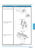
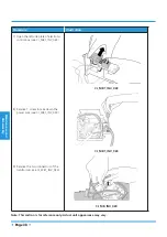
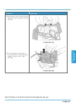
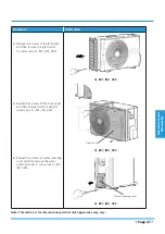
17) Release the 5 hooks in the back (see
CJ_MB1_INV_015).
18) Pull out the panel frame while
pushing the hook through a clearance
between the panel frame and the heat
exchanger. (see CJ_MB1_INV_016)
CJ_MB1_INV_015
CJ_MB1_INV_016
Note: This section is for reference only. Actual unit appearance may vary.
Summary of Contents for MISSION2 3D INVERTER Series
Page 2: ......
Page 4: ......
Page 11: ...Specifications Page 7 MOB01 09HFN1 MW0W MOB01 12HFN1 MV0W MOCA01 18HFN1 MT0W...
Page 12: ...Specifications Page 8 MOD01 23HFN1 MT0W...
Page 15: ...Specifications Page 11 PCB board of MOD01 23HFN1 MT0W...
Page 16: ...Specifications Page 12 IPM board of MOD01 23HFN1 MT0W...

