


67
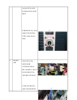
5) Turn on the vacuum pump to begin
evacuation.
6) Conduct a 30-minute evacuation. Check
whether the compound meter indicates
-0.1Mpa(14.5Psi). If the meter does not
indicate -0.1Mpa(14.5Psi) after 30 minutes
has elapsed, continue evacuation for 20
more minutes. If the pressure does not
reach -0.1Mpa(14.5Psi) after 50 minutes
has elapsed, check if there are any leaks.
Fully close the Handle Lo valve of the manifold
valve and turn off the vacuum pump. After 5
minutes, confirm that the gauge needle is not
moving.
7) Turn the flare nut on the 3-way valve45°
counterclockwise for 6-7 seconds. Once
gas begins to come out, tighten the flare nut.
Make sure the pressure display on the
pressure
indicator
is
higher
than
atmospheric pressure. Then remove the
charge hose from the 3-way valve.
8) Fully open the 2-wayand 3-way valves and
securely tighten the cap on the 3-way valve.
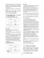
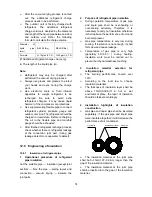
2. Air Purging Using Refrigerant
Procedure:
1). Confirm that both the 2-way and 3-way
valves are set to the closed position.
2). Connect the charge set and a charging
cylinder to the service port on the 3-way valve.
3). Air purging:
Open the valves on the charging cylinder and
the charge set. Loosen the flare nut on the
2-way valve approximately 45° for 3 seconds
then closing it for 1 minute. Repeat 3 times.
After purging the air, use a torque wrench to
tighten the flare nut on the 2-way valve.
4). Check for gas leaks.
Check the flare connections for gas leaks.
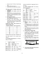
5). Discharge the refrigerant.
Close the valve on the charging cylinder and
discharge the refrigerant by loosening the flare
nut on the 2-way valve approximately 45° until
the gauge displays a value between 0.3 to 0.5
Mpa(43.5 to 72.5Psi)
6). Disconnect the charge set and the charging
cylinder. Set the 2-way and 3-way valves to the
open position.
Be sure to use a hexagonal wrench to open and
close the valve stems.
7). Mount the valve stems nuts and the service
port cap.
Be sure to use a torque wrench to tighten the
service port cap to a torque of 18N·m.
Be sure to check for gas leaks.
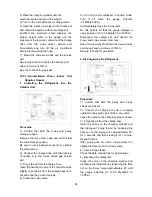
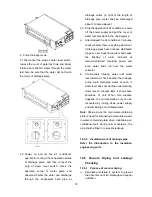
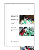
12.4.4 Adding Refrigerant after Long-Term
System Operation
Procedure
1). Connect the charge hose to the 3-way
service port and open the 2-way and 3-way
valve.
Connect the charge hose to the valve at the
bottom of the cylinder. If the refrigerant is
R410A, place the cylinder bottom-up to ensure
liquid charge.
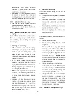
2). Purge the air from the charge hose.
Open the valve at the bottom of the cylinder
and press the check valve on the charge set to
purge the air (be careful of the liquid
refrigerant).
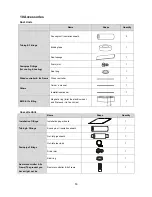
Summary of Contents for MCHSU-09PHH2
Page 7: ...5 2 2 Part names of Indoor Outdoor units Cassette Unit...
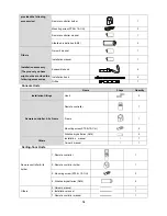
Page 8: ...6 Duct Units...
Page 9: ...7 Console...
Page 10: ...8 Ceiling floor Units...
Page 28: ...26 Console Unit Ceiling floor Units 39 37 39 37in 3 94in 39 37in 1 38in...
Page 32: ...30 MEHSU 09CHN2 MEHSU 12CHN2 MEHSU 36CSC2 MEHSU 48CSC2...
Page 33: ...31 MEHSU 36CSD2 MEHSU 48CSD2...
Page 34: ...32 MEHSU 18CHF2 MEHSU 24CHF2 MEHSU 36CSF2...
Page 35: ...33 MEHSU 48CSF2 MEHSU 36CSF2 MEHSU 48CSF2...
Page 36: ...34 6 2 Outdoor Unit MCHSU 09PHH2 MCHSU 12PHH2 MCHSU 18PHH2...
Page 37: ...35 MCHSU 24PHH2...
Page 38: ...36 MCHSU 36CSH2...
Page 41: ...39 For MCHSU 48CSH2...
Page 44: ...42 MEHSU 09CHD2 Code 0 Code 1 Code 2 Code 3 Code 4...
Page 45: ...43 MEHSU 12CHD2 Code 0 Code 1 Code 2 Code 3 Code 4...
Page 46: ...44 MEHSU 18CHD2 Code 0 Code 1 Code 2 Code 3 Code 4...
Page 47: ...45 MEHSU 24CHD2 Code 0 Code 1 Code 2 Code 3 Code 4...
Page 48: ...46 MEHSU 36CSD2 Code 0 Code 1 Code 2 Code 3 Code 4...
Page 49: ...47 MEHSU 48CSD2 Code 0 Code 1 Code 2 Code 3 Code 4...
Page 58: ...56 12 Field Wiring 36K 48K...