6
Figure 5-1
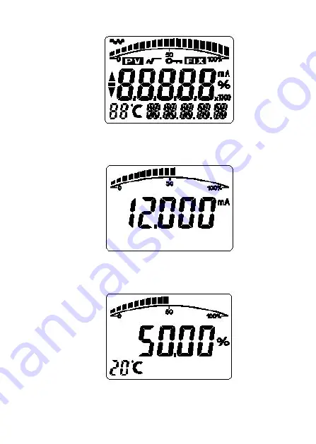
Current display see Figure 5-2
Figure 5-2
Main volume percentage display see Figure 4-3
Figure 5-3
Main volume display see Figure 5-4
Page 1: ...V2 0 MPM486 Operation Manual...
Page 2: ...surements and industry process controls system requiring BUS operation with HART protocol in the fields of petroleum chemo industry electric power and paper making etc The unit can be compatible with...
Page 3: ...mmunication Display LCD Display Two Three keys controls Damp 0s 32s Load U 12V 0 02 Insulation 100M 50V Endurance 1x10⁷ pressure cycle 0 FS 100 FS 25 Vibration 20g 20 5000 Hz Shock 20g 11ms Protection...
Page 4: ...necting with the anode of Supply terminal A on the left Signal I out connecting the signal terminal B Be sure the Supply Signal wires DO NOT connecting with the TEST terminal Otherwise it will make th...
Page 5: ...mitter is not strict even if the voltage wave around 1V the influence on output signal is very small or can be ignored The transmitter is capacitive coupled grounded while you are checking the insulat...
Page 6: ...guration software to set the volume and the decimal point of LCD display Referring to the words of meter configuration to output of configuration software LCD allows the double volumes displaying The...
Page 7: ...6 Figure 5 1 Current display see Figure 5 2 Figure 5 2 Main volume percentage display see Figure 4 3 Figure 5 3 Main volume display see Figure 5 4...
Page 8: ...display the temperature 88 below 19 or over 99 display 6 Local Adjustment It is possible to set the unit range damp etc and adjust the zero zero and span elevation functions also you can look above v...
Page 9: ...ress down S key will enter data setting then symbol starts flashing and you can change symbol 2 If press down S key again you can exchange data s and means 3 Press down Z key the first number begins t...
Page 10: ...not you have to wait for the next down arrows flashing to store your settings 6 3 Local Adjustment 6 3 1 Data setting In local adjustment LCD left down 88 will show setting data types the correspondin...
Page 11: ...ass code of configuration data setting is 00002 when it is correct you can start data setting if not it will be back to normal display If the setting data is over the limitation LCD display OVER then...
Page 12: ...BAR 0 000 2 MPA 0 002 2 ATM 1 865 2 TORR 0 249 2 KPA S key S key M key or Z key S key S key S key S key S key S key S key S key S key S key S key S key S key S key S key S key S key S key S key S key...
Page 13: ...edure Figures 2 zero and span elevation In the normal display state press down Z and S key at the same time then entering the zero and span elevation state the procedure see Figure 5 3 4 normal displa...
Page 14: ...finger or a sharp tool it will damage the sensor 4 If the transmitter application site is near strong interfere be sure the electronic housing grounded well 8 Warranty Within one year from the delive...
Page 15: ...tion etc set range unit the up down range limitation and transmitter series number setting zero and span elevation to transmitter setting transmitter s damp output specification and displaying volume...
Page 16: ......
Page 17: ......