


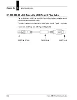
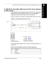


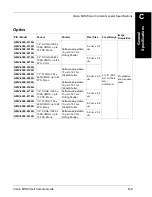
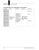
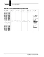
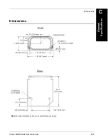

Appendix
B
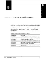
Cable Specifications
B-4
Vision MINI Smart Camera Guide
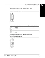
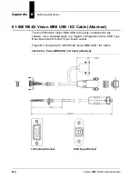
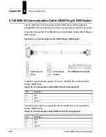
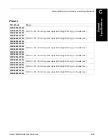
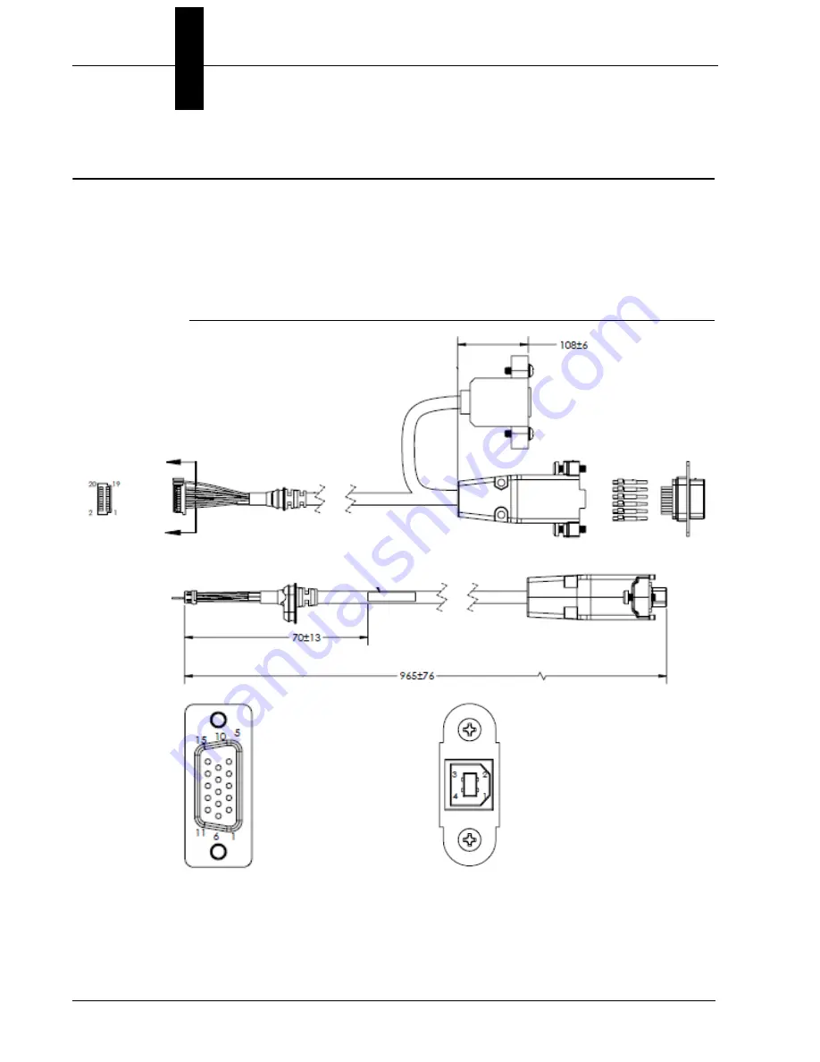
61-000196-02 Vision MINI USB / I/O Cable (Attached)
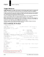
The 61-000196-02 Vision MINI USB / I/O Cable is attached to the
camera. It is a shielded cable in a “pigtail” configuration with a USB Type
B socket and an RS-232 15-pin D-sub socket.
Figure B-3 shows the 61-000196-02 Vision MINI USB / I/O Cable.
FIGURE B–3.
Vision MINI USB / I/O Cable (Attached)
15-Pin D-sub Socket
USB Type B Socket
Summary of Contents for Vision MINI Smart Camera
Page 1: ...Vision MINI Smart Camera Guide 84 016300 02 Rev J ...
Page 16: ...Chapter 2 System Components 2 6 Vision MINI Smart Camera Guide Direct Input Output Diagrams ...
Page 18: ...Chapter 2 System Components 2 8 Vision MINI Smart Camera Guide New Master Input with IC 332 ...
Page 24: ...Chapter 2 System Components 2 14 Vision MINI Smart Camera Guide ...
Page 32: ...Appendix A Connector Pinouts A 4 Vision MINI Smart Camera Guide ...
Page 42: ...Appendix B Cable Specifications B 10 Vision MINI Smart Camera Guide ...
Page 62: ...Appendix E Vision MINI Diagnostic Boot Mode E 4 Vision MINI Smart Camera Guide ...
Page 66: ...Appendix F USB Power Management F 4 Vision MINI Smart Camera Guide ...


