


Chapter
2
System Components
2-4
Vision MINI Smart Camera Guide
Back
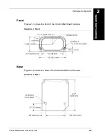
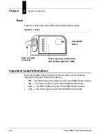
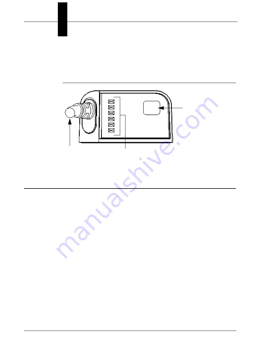
Figure 2-3 shows the back of the Vision MINI Smart Camera.
FIGURE 2–3.
Back
Important Label Information
Each Vision MINI Smart Camera has its own label, which contains
important information about that camera.
•
P/N – The Microscan part number of your Vision MINI Smart Camera.
•
S/N — The serial number of your Vision MINI Smart Camera.
•
MAC — The MAC address of your Vision MINI Smart Camera.
•
Type — The model type of your Vision MINI Smart Camera.
USB / I/O cable
(attached)
AutoVISION
Button
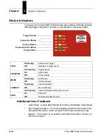
Status Indicators (TRIG, PASS,
FAIL, MODE, LINK/ACT, PWR)
Summary of Contents for Vision MINI Smart Camera
Page 1: ...Vision MINI Smart Camera Guide 84 016300 02 Rev J ...
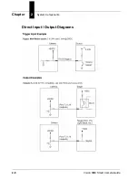
Page 16: ...Chapter 2 System Components 2 6 Vision MINI Smart Camera Guide Direct Input Output Diagrams ...
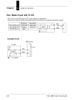
Page 18: ...Chapter 2 System Components 2 8 Vision MINI Smart Camera Guide New Master Input with IC 332 ...
Page 24: ...Chapter 2 System Components 2 14 Vision MINI Smart Camera Guide ...
Page 32: ...Appendix A Connector Pinouts A 4 Vision MINI Smart Camera Guide ...
Page 42: ...Appendix B Cable Specifications B 10 Vision MINI Smart Camera Guide ...
Page 62: ...Appendix E Vision MINI Diagnostic Boot Mode E 4 Vision MINI Smart Camera Guide ...
Page 66: ...Appendix F USB Power Management F 4 Vision MINI Smart Camera Guide ...


