2: Installation
U3000/U4000 User Manual
9
(Issue 2.0)
2.2.3 Connecting the instrument
All cables enter the instrument through the (4) cable glands provided and are connected to terminal blocks
which are located behind a safety cover. The terminal blocks use a spring-loaded securing mechanism which
is opened by lifting the orange tab situated on the top of the terminal connection.
Control & monitoring cables
Depending on the fitted options, any of the following control and monitoring cables may be required:
•
Current output
– a 4-20mA, 0-16mA, or 0-20mA monitoring signal is output at terminal
mA+
and
mA-
.
(
mA+
is the current output terminal and
mA
- is the return terminal).
•
Pulse output
– an opto-isolated pulse output is available at terminals
PULSE+
and
PULSE-
(
PULSE+
is
the pulse output terminal and
PULSE-
is the return terminal).
•
Alarm Outputs
– two programmable, multifunction alarm outputs are available using MOSFET, SPNO
relays. The relays are rated at 48V/500mA continuous load, and are connected to terminals
, ALARM1-, and ALARM2- respectively.
•
RS232 Interface (U4000 only)
– an RS232 interface is provided to allow logged data to be
downloaded to a PC or RS232 compatible printer. The interface is connected to terminal
TxD
(data
transmitted from the U4000)
RxD
(data received by the U4000) and
GND
(signal ground).
•
Expansion ports (U4000 only)
– terminals
EXPIO#1
to
EXPIO#8
are used for I/O connections to a
number of optional expansion boards that may be fitted to the U4000 expansion slot. Details of the
available options are provided in Chapter 7.
1.
Remove the terminal block cover.
2.
Route the control and monitoring cables through the two smaller cable glands.
3.
Cut the wires to length, strip back the insulation by approximately 10mm and connect them into the
required terminals as described above and identified in
Figure 2.1
.
4.
On completion, tighten the cable glands to ensure the cables are held securely.
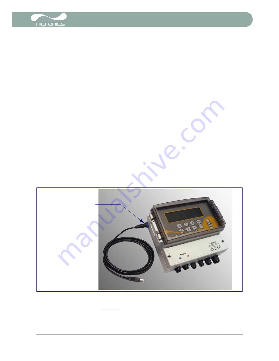
USB Connection (U4000 only)
Figure 2.2 U4000 USB Connection
A Mini-USB connector is available at the left-hand side of the enclosure to which the USB cable provided can
be attached, as shown in
Figure 2.2
. The free end of the USB cable can be plugged directly into any PC USB
port.
USB Connector


