5
•
Logger included as standard.
•
Power supply - with UK, US, European
adapters. 110/240VAC.
•
Ultrasonic couplant.
•
Manual.
•
4 lengths of chain each at 3.3 metres long
•
Sensor cables 2 metres long.
•
4-20mA, Pulse Output and RS232-C
cables.
Options
•
Guide Rail Assembly ‘A’ - Includes sensors
for pipe ID 13mm to 89mm. Temperature
range -20°C to +200°C.
•
Guide Rail Assembly ‘B’ - Includes sensors
for pipe ID 90mm to 1000mm.
Temperature range -20°C to +200°C.
•
Guide Rail for use in Diagonal Mode
•
Magnetic assembly - Diagonal and ‘B’
guide rail Assembly.
•
Transducer set ‘C’ - High Velocity
Transducers for pipes 300mm to 2000mm,
in guide rail ‘B’.
•
Transducer kit ‘D’ - Sensors include
ratchet straps for pipes 1000mm to
5000mm. Temp range -20°C to +80°C.
•
Extra chain is available on request.
•
Calibration certificate with (NAMAS
accreditation)
Charger
(Use only the charger supplied.)
The battery takes 15 hours to fully charge.
When the instrument is charging, but switched
off, the display reads ‘CHARGING
’.
It also
displays a battery and plug
symbol.
CHARGING is displayed under the word
‘Battery’ when on charge in flow mode, and a
‘plug’ symbol is displayed in place of the
battery symbol.
Battery
When you first receive your unit put the battery
on charge for a minimum of 15hrs. When fully
charged the battery will last up to 24hrs,
depending on the outputs used and how often
the backlight is operated. If the backlight has
been enabled, every time a key is pressed it
comes on for 15 seconds. If the backlight is
active continuously the battery life would
reduce to 8hrs. If the 4-20mA is used
constantly at 20mA, the battery life would
reduce by 20%.
The display in flow mode continually shows the
battery level as a percentage. When this
indication reads approximately 40%, it will
display a warning message. This indicates
there is only 30 minutes of use left in the
battery. The battery can be charged while the
instrument is in use or while the instrument is
switched off. The battery can also be partially
charged and then used.
Keypad
Programming is via the tactile membrane
keypad with rim embossed keys. The keypad
is rated at IP67.
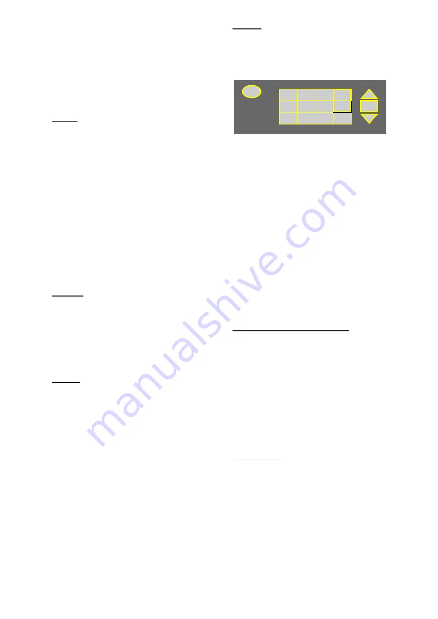
Figure 7
PORTAFLOW
300
0
Pulse
6
5
4
Velocity
7
Litres
8
Gallons
9
m
3
3
4 - 20mA
2
RS 232
1
Logger
Delete
+/-
Options
ON/OFF
ENTER
scroll
scroll
.
MICRONICS LTD
By selecting keys
4, 7
,
8
and
9
it is possible to
change the velocity and volumetric flow
reading. Press the key more than once to
change the display.
•
Press
4 >
m/s, press
4 >
f/s
•
Press
7
>
l/s, press
7
>
l/min
•
Press
8
>
g/min, press
8
>
USG/min
•
Press
9
>
m
3
/hr, press
9 >
m
3
/min, press
9
>
m
3
/sec
There are also some facilities that require you
to move the cursor on the display left and right
as well as up and down. This is done with keys
5
(left) and
6
(right).
The 4-20mA, Pulse, RS232 and logger keys
can only be activated from flow mode (See
page 19 - Keypad Options). The RS232 and
data logger is also on the MAIN MENU.
Temperature Indication/Range
The transducers work over two temperature
ranges. The standard temperature range is
from -20°C to +200°C. The high temperature
range is from -20°C to +200°C. When in flow
mode the application temperature is only
displayed if the prop/temp sensor cable is
connected. Inside the transducer block is the
PT100 sensor, which produces the
temperature reading. This reading will change
if the temperature of the application changes.
The instrument can only compensate for a
temperature change of
±
10°C when reading
flow.
Transducers
The Portaflow 300 uses four different
transducer sets. They are called ‘A’, ‘B’, ‘C’
and ‘D’. The instrument selects transducer
sets, depending on the data entered (i.e. the
pipe size and flow velocity). There are default
pipe ranges programmed into the instrument
and most of the time there will be no need to
change these. However it is possible to use
different transducer sets on different pipe sizes
outside their normal operating range (See
page 9 - Select Sensor Set). The Portaflow
300 will only let you use the sensors supplied
with the instrument. If other sensors were
required software information would be


