background image

NO

NO

NO

NO

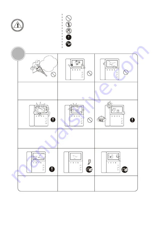
The socket holes
 are lager than
 usual.

If the socket holes are larger
than normal, do not put the
plug.
It may cause an electric shock 
or a fire. 

Make sure that dust or foreign
substances are not gathered
on the product.

Make sure to prevent foreign
substances from entering the
product.
It may cause a breakdown.

Do not put a heavy object on
the product.
It may cause a breakdown.

Do not disassemble the
 product.

Avoid direct rays of the sun or
heating devices at a time of
installation.

Install the product in a flat and
stable place.
Otherwise, it may not function 
properly.

Pull the plug if the product is
not used for a long time.

If the product generates 
strange


sound, make sure to 

pull the


plug immediately and 

contact


 service


center.

CAUTION

Caution

A injury or property
losses are expected.

It indicates prohibition of contact.

It indicates disassembly.

It indicates dos and don’ts.

It indicates that the plug should be pulled out from the
 socket.

It indicates prohibition.

Page2

Summary of Contents for IMATB4H

Page 1: ...ucts The company is not responsible for any safety accidents caused by abnormal operation of the product Please carefully read this User s Guide in particular precautions for safety before using this product COLOR VIDEO DOOR PHONE Model no IMATB4H ...

Page 2: ...ersion1 1 6 Installation 9 System setting 1 Warning and Caution Index 10 Specification 2 The function and name of each part 7 Buttons function 8 Operation guide 3 Features and main function 4 Package contents 5 Wiring diagram ...

Page 3: ...orcibly pull out the cord from the socket If the cord is damaged it may cause a fire or an electric shock Do not put the plug in the socket with a wet hand It may cause an electric shock Do not disassemble repair or modify the product It may cause a fire an electric shock or an injury due to malfunction of the product Do not use AC circuit breaker It may cause an electric shock warning warning 1 W...

Page 4: ...not disassemble the product Avoid direct rays of the sun or heating devices at a time of installation Install the product in a flat and stable place Otherwise it may not function properly Pull the plug if the product is not used for a long time If the product generates strange sound make sure to pull the plug immediately and contact service center CAUTION Caution A injury or property losses are ex...

Page 5: ... Menu button Item Function description 7 8 9 10 11 Enter system settings Confirm Unlock button Answer button Monitor button Indicator light Microphone Choose Adjust Back Hang up Unlock Answer Call Monitor Power indicator light Page 3 2 The function and name of each part 1 2 3 4 5 10 9 8 7 6 1 1 2 1 Front view ...

Page 6: ...1 Port 2 Port 3 Port 4 PWR1 VD1 DATA GND AD1 GND PWR2 VD2 AD2 CCTV2 CCTV1 GND GND DATA GND VD AD GND VCC Port 1 Port 2 Port 3 Port 4 For connecting IMARJ 3 Speaker 2 4 Microphone For connecting slave monitor For connecting power supply 1 Speaker 1 1 2 Ports 2 2 1 Rear view Ports detail Page 4 ...

Page 7: ...eet different people s favor Friendly interface simple operation 12 polyphonic ring tones switch freely 3 1 Features 3 2 Main function Unlock Broadcast function Monitor listening Call transfer Real time monitoring to doorbell or CCTV camera Make internal call to other monitors Brightness contrast volume display model and color adjustable ...

Page 8: ... A D 1 DATA GND PWR VD1 IMARJ 5 Wiring Diagram Page 6 IMAPS PWR1 VD1 DATA GND AD1 Port 1 IMAMD V OUT V IN M4 M3 M2 M1 IMAMD V OUT V IN M4 M3 M2 M1 5 wires 5 wires 5 wires 5 wires 5 wires Cat 5 Cat 5 Cat 5 Cat 5 Cat 5 Cat 5 Cat 5 Cat 5 Welcome RF M1 M2 M3 M4 ON 1 2 The DIP switch in the last IMAMD should set to be ON ...

Page 9: ...st distance between indoor monitor and doorbell is at least 350 mm 3 Ensure no power supply connection before installation finished 4 Take off the bracket from the back of the monitor 5 Install the bracket on the wall 6 Connect cables as per the wiring diagram indicated 7 Fix the monitor onto the bracket 8 Power on the monitor when the system wiring finished 6 Installation 150cm Page 7 ...

Page 10: ...door station Press it again can swtich to other monitoring Long installed press will enable the listening mode Only works when slave monitors are Answer button Press this button to answer the call Short press can make internal call to other monitors long press can make broadcast in standby mode Only works when slave monitors are installed Unlock button The tenant can press this button to turn on t...

Page 11: ...y number button to enter debug setting press any number button to enable DEBUG MODE Long presss until the screen shows SYSTEM SETUP Then go to the monitor system settings press or to go to ROOM NO setting press to enter it to change the ROOM NO Remark The ROOM NO could only be modified when the door station screen shows SYSTEM SETUP Talking volume adjust At the state of monitoring ringing talking ...

Page 12: ...k the door for the visitor press or to enter volume adjustment interface Press can switch to BRIGHT CONT COLOR display model interface press or to adjust as the user wants Don t disturb function You can use SYSTEM SETTINGS menu to turn DO NOT DISTURB function on or off If enable this function there will be no chime during ringing intercom broadcast Monitor door station CCTV camera At standby state...

Page 13: ...s will show BROADCASTING Now you can make broadcast Remark At broadcast state it s only one way talk The listener can not talk to the caller At standby state long press button to start the monitor listening function If you have more than 2 indoor monitors there would be option rooms for Monitor listening choosing on screen press or to choose the target indoor intercom and press to confirm Note a Wh...

Page 14: ...y default at the ringing intercom between monitors broadcast status the LED indicator will flicker when turn on DO NOT DISTURB function 5 CAN BE MONITORED Off by default it can be monitored by other indoor intercoms in the system when turn on this function 6 DEVICE ADDRESS Room1 2 3 4 Master monitor must be set as ROOM 1 and the option will be yellow if two monitors set the same address 7 8 RESTORE...

Page 15: ...ency Range 400 3 5K 8 Intercom distance 30m RVV4 0 5 100m RVV2 0 5 SYV75 3 9 Video 1Vp p 75OHM Input 10 Button Touch buttons 11 Outdoor panel Support 2 5PIN 1 4PIN 1 12 CCTV Support 2 channels 13 Ringtones 12 Polyphonic ringtones 15 Operating voltage DC14 5V 0 8A 16 Power Consumption 5W Max 0 3W Standby 17 Operating temperature 10 40 18 Storage Temperature 30 60 10 Specification Page 13 ...

Page 16: ...The parameters of product are subject to changes without prior notice ...

Reviews: