PICDEM Touch Sense 2 Demo Board User’s Guide
DS51748A-page 20
©
2008 Microchip Technology Inc.
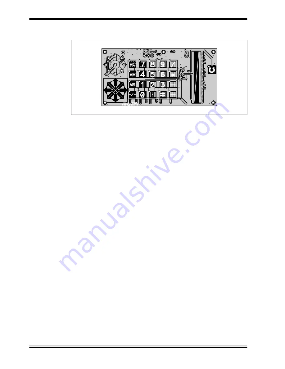
FIGURE 4-2:
TOUCH SENSE 2 DEMO BOARD, WITH TOP ACRYLIC
COVER REMOVED TO SHOW SENSORS
Nine of the A/D channels are used to monitor the numeric keypad switches (S1 through
S12 and S21 through S27), arranged in a 4x5 array. Each “switch” is composed of
interleaved conductors from two channels. The location of the touched key is
determined by a simultaneous capacitance change on any two channels.
Four channels are used to monitor the directional keypad. The sensor consists of four
arrow shaped, dual capacitive touch pads, oriented at the four cardinal compass points
(N, E, S and W), with capacitive touch pads at the adjacent four compass points (NE,
SE, SW and NW) and in the center. Touch events on the cardinal points causes a
capacitance change in the corresponding channel. Touches between the cardinal
points, or in the center, are interpolated from simultaneous changes on two adjacent
channels, or all four channels, respectively.
Two channels are used to monitor the touch slider, S14. The slider is composed of two
large and adjacent capacitive touch pads, tapering from one side to the other and in
opposite directions. The location of a touch event on the slider is determined by the
differential change in capacitance between the channels.
The remaining A/D channel is used to monitor the demo board’s “soft” power switch,
S20; this is an interleaved capacitive touch pad similar to those in the numeric keypad.
When power is applied to the Touch Sense 2 Demo Board, the microcontroller
immediately initializes the demo application and starts in Full-Power mode. When the
power switch is pressed and held for approximately 3 seconds, the microcontroller
goes into Low-Power Sleep mode, monitoring S20 at intervals of 50 milliseconds. A
touch event on S20 causes the application to wake again to full-power operation.
When an event occurs, the application firmware also provides feedback by activating
one or more LEDs at that location. A total of 61 LEDs are driven directly by the
microcontroller through pins on PORTC, PORTD, PORTE and PORTG. The LEDs for
the numeric keypad are driven as a 4x5 matrix from PORTE, using 5 lines to source
current and four to sink current. Individual LEDs are used for the directional keypad and
the power switch.
The linear LED display on the touch slider is driven in a method similar to those of the
numeric keypad, using a 4x4 matrix on PORTD. Each node has two LEDs, connected
in forward and reverse-biased pairs. To light a specific diode in each pair, the row and
column ports are toggled to act as current sources or sinks, causing one diode or the
other to be properly biased.
In addition to visual feedback, the demo board also provides audible feedback for each
touch event on the numeric keypad. An audio signal is generated using one of the
microcontroller’s PWM module, and directly drives the piezo speaker BZ1 through pin
RG7.


