


PIC16F87XA
DS39582B-page 154
2003 Microchip Technology Inc.
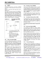
14.11.1
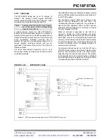
INT INTERRUPT
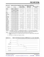
External interrupt on the RB0/INT pin is edge triggered,
either rising if bit INTEDG (OPTION_REG<6>) is set or
falling if the INTEDG bit is clear. When a valid edge
appears on the RB0/INT pin, flag bit, INTF
(INTCON<1>), is set. This interrupt can be disabled by
clearing enable bit, INTE (INTCON<4>). Flag bit INTF
must be cleared in software in the Interrupt Service
Routine before re-enabling this interrupt. The INT
interrupt can wake-up the processor from Sleep if bit
INTE was set prior to going into Sleep. The status of
global interrupt enable bit, GIE, decides whether or not
the processor branches to the interrupt vector following
wake-up. See Section 14.14 “Power-down Mode
(Sleep)” for details on Sleep mode.
14.11.2
TMR0 INTERRUPT
An overflow (FFh
→
00h) in the TMR0 register will set
flag bit, TMR0IF (INTCON<2>). The interrupt can be
enabled/disabled by setting/clearing enable bit,
TMR0IE (INTCON<5>). See Section 5.0 “Timer0
Module”.
14.11.3
PORTB INTCON CHANGE
An input change on PORTB<7:4> sets flag bit, RBIF
(INTCON<0>). The interrupt can be enabled/disabled
by setting/clearing enable bit, RBIE (INTCON<4>). See
Section 4.2 “PORTB and the TRISB Register”.
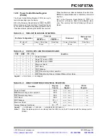
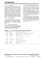
14.12 Context Saving During Interrupts
During an interrupt, only the return PC value is saved
on the stack. Typically, users may wish to save key reg-
isters during an interrupt (i.e., W register and Status
register). This will have to be implemented in software.
For the PIC16F873A/874A devices, the register
W_TEMP must be defined in both Banks 0 and 1 and
must be defined at the same offset from the bank base
address (i.e., If W_TEMP is defined at 0x20 in Bank 0,
it must also be defined at 0xA0 in Bank 1). The regis-
ters, PCLATH_TEMP and STATUS_TEMP, are only
defined in Bank 0.
Since the upper 16 bytes of each bank are common in
the PIC16F876A/877A devices, temporary holding reg-
isters, W_TEMP, STATUS_TEMP and PCLATH_TEMP,
should be placed in here. These 16 locations don’t
require banking and therefore, make it easier for con-
text save and restore. The same code shown in
Example 14-1 can be used.
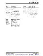
EXAMPLE 14-1:
SAVING STATUS, W AND PCLATH REGISTERS IN RAM
MOVWF W_TEMP ;Copy W to TEMP register
SWAPF STATUS,W ;Swap status to be saved into W
CLRF STATUS ;bank 0, regardless of current bank, Clears IRP,RP1,RP0
MOVWF STATUS_TEMP ;Save status to bank zero STATUS_TEMP register
MOVF PCLATH, W
;Only required if using pages 1, 2 and/or 3
MOVWF PCLATH_TEMP ;Save PCLATH into W
CLRF PCLATH ;Page zero, regardless of current page
:
:(ISR)
;(Insert user code here)
:
MOVF PCLATH_TEMP, W
;Restore PCLATH
MOVWF PCLATH
;Move W into PCLATH
SWAPF STATUS_TEMP,W
;Swap STATUS_TEMP register into W
;(sets bank to original state)
MOVWF STATUS
;Move W into STATUS register
SWAPF W_TEMP,F
;Swap W_TEMP
SWAPF W_TEMP,W
;Swap W_TEMP into W
http://www.xinpian.net
提供单片机解密、IC解密、芯片解密业务
010-62245566 13810019655


