


2003 Microchip Technology Inc.
Preliminary
DS41206A-page 59
PIC16F716
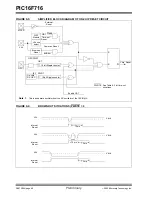
9.5
Power-up Timer (PWRT)
The Power-up Timer provides a fixed nominal time-out,
on power-up only, from the POR. The Power-up Timer
operates on an internal RC oscillator. The chip is kept
in Reset as long as the PWRT is active. The PWRT’s
time delay allows V
DD
to rise to an acceptable level.
The power-up timer enable configuration bit, PWRTE,
is provided to enable/disable the PWRT.
The power-up time delay will vary from chip-to-chip due
to V
DD
, temperature and process variation. See AC
parameters for details.
9.6
Oscillator Start-up Timer (OST)
The Oscillator Start-up Timer (OST) provides a 1024
oscillator cycle (from OSC1 input) delay after the
PWRT delay is over. This ensures that the crystal
oscillator or resonator has started and stabilized. See
AC parameters for details.
The OST time-out is invoked only for XT, LP and HS
modes and only on Power-on Reset or wake-up from
Sleep.
9.7
Programmable Brown-Out Reset
(PBOR)
The PIC16F716 has on-chip Brown-out Reset circuitry.
A configuration bit, BOREN, can disable (if clear/pro-
grammed) or enable (if set) the Brown-out Reset
circuitry.
The BORV configuration bit selects the programmable
Brown-out Reset threshold voltage (V
BOR
). When
BORV is 1, V
BOR
IS
4.0V. When BORV is 0, V
BOR
is
2.5V
A Brown-out Reset occurs when V
DD
falls below V
BOR
for a time greater than parameter T
BOR
A Brown-out Reset is not guaranteed to occur if V
DD
falls
below V
BOR
for less than parameter T
BOR
.
On any Reset (Power-on, Brown-out, Watchdog, etc.)
the chip will remain in Reset until V
DD
rises above
V
BOR
. The Power-up Timer will be invoked and will
keep the chip in Reset an additional 72 ms only if the
Power-up Timer enable bit in the configuration register
is set to 0 (PWRTE =
0
).
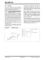
If the Power-up Timer is enabled and V
DD
drops below
V
BOR
while the Power-up Timer is running, the chip will
go back into a Brown-out Reset and the Power-up
Timer will be re-initialized. Once V
DD
rises above V
BOR
,
the Power-up Timer will execute a 72 ms Reset. See
Figure 9-6.
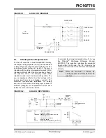
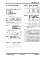
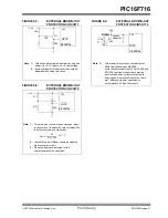
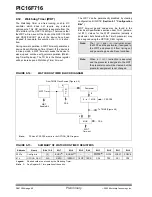
For operations where the desired brown-out voltage is
other than 4.0V or 2.5V, an external brown-out circuit
must be used. Figure 9-8, Figure 9-9 and Figure 9-10
show examples of external Brown-out Protection
circuits.
Summary of Contents for PIC16F716
Page 6: ...PIC16F716 DS41206A page 4 Preliminary 2003 Microchip Technology Inc NOTES...
Page 35: ......
Page 56: ......
Page 60: ......
Page 88: ......
Page 92: ...PIC16F716 DS41206A page 90 Preliminary 2003 Microchip Technology Inc NOTES...
Page 108: ...PIC16F716 DS41206A page 106 Preliminary 2003 Microchip Technology Inc NOTES...
Page 110: ...PIC16F716 DS41206A page 108 Preliminary 2003 Microchip Technology Inc NOTES...
Page 124: ...PIC16F716 DS41206A page 122 Preliminary 2003 Microchip Technology Inc NOTES...


