


2000 Microchip Technology Inc.
DS30605C-page 49
PIC16C63A/65B/73B/74B
9.0
CAPTURE/COMPARE/PWM
MODULES
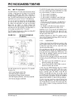
Each Capture/Compare/PWM (CCP) module contains
a 16-bit register which can operate as a:
• 16-bit Capture register
• 16-bit Compare register
• PWM Master/Slave Duty Cycle register
Both the CCP1 and CCP2 modules are identical in
operation, with the exception being the operation of the
special event trigger. Table 9-1 and Table 9-2 show the
resources and interactions of the CCP module(s). In
the following sections, the operation of a CCP module
is described with respect to CCP1. CCP2 operates the
same as CCP1, except where noted.
CCP1 Module:
Capture/Compare/PWM Register1 (CCPR1) is com-
prised of two 8-bit registers: CCPR1L (low byte) and
CCPR1H (high byte). The CCP1CON register controls
the operation of CCP1. The special event trigger is
generated by a compare match and will reset Timer1.
CCP2 Module:
Capture/Compare/PWM Register2 (CCPR2) is com-
prised of two 8-bit registers: CCPR2L (low byte) and
CCPR2H (high byte). The CCP2CON register controls
the operation of CCP2. The special event trigger is
generated by a compare match and will reset Timer1
and start an A/D conversion (if the A/D module is
enabled).
Additional information on CCP modules is available in
the PICmicro™ Mid-Range MCU Family Reference
Manual (DS33023) and in “Using the CCP Modules”
(AN594).
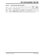
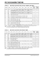
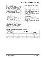
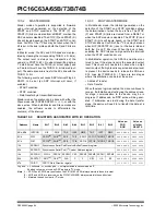
TABLE 9-1:
CCP MODE - TIMER
RESOURCES REQUIRED
TABLE 9-2:
INTERACTION OF TWO CCP MODULES
CCP Mode
Timer Resource
Capture
Compare
PWM
Timer1
Timer1
Timer2
CCPx Mode CCPy Mode
Interaction
Capture
Capture
Same TMR1 time-base.
Capture
Compare
The compare should be configured for the special event trigger, which clears TMR1.
Compare
Compare
The compare(s) should be configured for the special event trigger, which clears TMR1.
PWM
PWM
The PWMs will have the same frequency and update rate (TMR2 interrupt).
PWM
Capture
None.
PWM
Compare
None.
Summary of Contents for PIC16C63A
Page 4: ...PIC16C63A 65B 73B 74B DS30605C page 4 2000 Microchip Technology Inc NOTES ...
Page 6: ...PIC16C63A 65B 73B 74B DS30605C page 6 2000 Microchip Technology Inc NOTES ...
Page 8: ...PIC16C63A 65B 73B 74B DS30605C page 8 2000 Microchip Technology Inc NOTES ...
Page 28: ...PIC16C63A 65B 73B 74B DS30605C page 28 2000 Microchip Technology Inc NOTES ...
Page 42: ...PIC16C63A 65B 73B 74B DS30605C page 42 2000 Microchip Technology Inc NOTES ...
Page 78: ...PIC16C63A 65B 73B 74B DS30605C page 78 2000 Microchip Technology Inc NOTES ...
Page 112: ...PIC16C63A 65B 73B 74B DS30605C page 112 2000 Microchip Technology Inc NOTES ...
Page 152: ...PIC16C63A 65B 73B 74B DS30605C page 152 2000 Microchip Technology Inc NOTES ...
Page 164: ...PIC16C63A 65B 73B 74B DS30605C page 164 2000 Microchip Technology Inc NOTES ...
Page 174: ...PIC16C63A 65B 73B 74B DS30605C page 174 2000 Microchip Technology Inc NOTES ...
Page 178: ...PIC16C63A 65B 73B 74B DS30605C page 178 2000 Microchip Technology Inc NOTES ...
Page 179: ... 2000 Microchip Technology Inc DS30605C page 179 PIC16C63A 65B 73B 74B NOTES ...
Page 180: ...PIC16C63A 65B 73B 74B DS30605C page 180 2000 Microchip Technology Inc NOTES ...
Page 181: ... 2000 Microchip Technology Inc DS30605C page 181 PIC16C63A 65B 73B 74B NOTES ...
Page 182: ...PIC16C63A 65B 73B 74B DS30605C page 182 2000 Microchip Technology Inc NOTES ...
Page 183: ... 2000 Microchip Technology Inc DS30605C page 183 PIC16C63A 65B 73B 74B NOTES ...


