


2000 Microchip Technology Inc.
DS30605C-page 23
PIC16C63A/65B/73B/74B
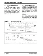
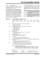
4.2.2.5
PIR1 Register
This register contains the individual flag bits for the
peripheral interrupts.
REGISTER 4-5:
PIR1 REGISTER (ADDRESS 0Ch)
Note:
Interrupt flag bits are set when an interrupt
condition occurs, regardless of the state of
its corresponding enable bit, or the global
enable bit, GIE (INTCON<7>). User soft-
ware should ensure the appropriate inter-
rupt flag bits are clear prior to enabling an
interrupt
.
R/W-0
R/W-0
R-0
R-0
R/W-0
R/W-0
R/W-0
R/W-0
PSPIF
(1)
ADIF
(2)
RCIF
TXIF
SSPIF
CCP1IF
TMR2IF
TMR1IF
bit 7
bit 0
bit 7
PSPIF
(1)
: Parallel Slave Port Read/Write Interrupt Flag bit
1
= A read or a write operation has taken place (must be cleared in software)
0
= No read or write has occurred
bit 6
ADIF
(2)
: A/D Converter Interrupt Flag bit
1
= An A/D conversion completed (must be cleared in software)
0
= The A/D conversion is not complete
bit 5
RCIF: USART Receive Interrupt Flag bit
1
= The USART receive buffer is full (clear by reading RCREG)
0
= The USART receive buffer is empty
bit 4
TXIF: USART Transmit Interrupt Flag bit
1
= The USART transmit buffer is empty (clear by writing to TXREG)
0
= The USART transmit buffer is full
bit 3
SSPIF: Synchronous Serial Port Interrupt Flag bit
1
= The transmission/reception is complete (must be cleared in software)
0
= Waiting to transmit/receive
bit 2
CCP1IF: CCP1 Interrupt Flag bit
Capture mode:
1
= A TMR1 register capture occurred (must be cleared in software)
0
= No TMR1 register capture occurred
Compare mode:
1
= A TMR1 register compare match occurred (must be cleared in software)
0
= No TMR1 register compare match occurred
PWM mode:
Unused in this mode
bit 1
TMR2IF: TMR2 to PR2 Match Interrupt Flag bit
1
= TMR2 to PR2 match occurred (must be cleared in software)
0
= No TMR2 to PR2 match occurred
bit 0
TMR1IF: TMR1 Overflow Interrupt Flag bit
1
= TMR1 register overflowed (must be cleared in software)
0
= TMR1 register did not overflow
Note 1: PIC16C63A/73B devices do not have a parallel slave port implemented. This bit loca-
tion is reserved on these devices.
2: PIC16C63A/65B devices do not have an A/D implemented. This bit location is
reserved on these devices.
Legend:
R = Readable bit
W = Writable bit
U = Unimplemented bit, read as ‘0’
-n = Value at POR
’1’ = Bit is set
’0’ = Bit is cleared
x = Bit is unknown
Summary of Contents for PIC16C63A
Page 4: ...PIC16C63A 65B 73B 74B DS30605C page 4 2000 Microchip Technology Inc NOTES ...
Page 6: ...PIC16C63A 65B 73B 74B DS30605C page 6 2000 Microchip Technology Inc NOTES ...
Page 8: ...PIC16C63A 65B 73B 74B DS30605C page 8 2000 Microchip Technology Inc NOTES ...
Page 28: ...PIC16C63A 65B 73B 74B DS30605C page 28 2000 Microchip Technology Inc NOTES ...
Page 42: ...PIC16C63A 65B 73B 74B DS30605C page 42 2000 Microchip Technology Inc NOTES ...
Page 78: ...PIC16C63A 65B 73B 74B DS30605C page 78 2000 Microchip Technology Inc NOTES ...
Page 112: ...PIC16C63A 65B 73B 74B DS30605C page 112 2000 Microchip Technology Inc NOTES ...
Page 152: ...PIC16C63A 65B 73B 74B DS30605C page 152 2000 Microchip Technology Inc NOTES ...
Page 164: ...PIC16C63A 65B 73B 74B DS30605C page 164 2000 Microchip Technology Inc NOTES ...
Page 174: ...PIC16C63A 65B 73B 74B DS30605C page 174 2000 Microchip Technology Inc NOTES ...
Page 178: ...PIC16C63A 65B 73B 74B DS30605C page 178 2000 Microchip Technology Inc NOTES ...
Page 179: ... 2000 Microchip Technology Inc DS30605C page 179 PIC16C63A 65B 73B 74B NOTES ...
Page 180: ...PIC16C63A 65B 73B 74B DS30605C page 180 2000 Microchip Technology Inc NOTES ...
Page 181: ... 2000 Microchip Technology Inc DS30605C page 181 PIC16C63A 65B 73B 74B NOTES ...
Page 182: ...PIC16C63A 65B 73B 74B DS30605C page 182 2000 Microchip Technology Inc NOTES ...
Page 183: ... 2000 Microchip Technology Inc DS30605C page 183 PIC16C63A 65B 73B 74B NOTES ...


