


MPLAB
®
ICD 3 User’s Guide for MPLAB X IDE
DS50002081B-page 18
2012-2014 Microchip Technology Inc.
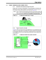
2.4.3
Target Powered
In the following descriptions, only three lines are active and relevant to core debugger
operation: pins 1 (V
PP
/MCLR), 5 (PGC) and 4 (PGD). Pins 2 (V
DD
) and 3 (V
SS
) are
shown on
for completeness. MPLAB ICD 3 has two configurations for
powering the target device: internal debugger and external target power.
The recommended source of power is external and derived from the target application.
In this configuration, target V
DD
is sensed by the debugger to allow level translation for
the target low-voltage operation. If the debugger does not sense voltage on its V
DD
line
(pin 2 of the interface connector), it will not operate.
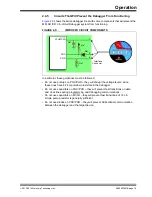
2.4.4
Debugger Powered
The internal debugger power is limited in two aspects:
- the voltage range is not as wide (3-5V)
- the amount of current it can supply is limited to 100 mA.
This may be of benefit for very small applications that have the device V
DD
separated
from the rest of the application circuit for independent programming. However, it is not
recommended for general usage because it imposes more current demands from the
USB power system derived from the PC.
Be aware that the target V
DD
is sensed by the debugger to allow level translation for
target low-voltage operation. If the debugger does not sense voltage on its V
DD
line (pin
2 of the interface connector), it will not allow communication with the target.
Not all devices have the AV
DD
and AV
SS
lines, but if they are present on the target
device, all must be connected to the appropriate levels in order for the debugger to
operate. They cannot be left floating.
In general, it is recommended that all V
DD
/AV
DD
and V
SS
/AV
SS
lines be connected to
the appropriate levels. Also, devices with a V
CAP
line (PIC18FXXJ MCUs, for example)
should be connected to the appropriate capacitor or level.
Note:
The interconnection is very simple. Any problems experienced are often
caused by other connections or components on these critical lines that
interfere with the operation of the MPLAB ICD 3 In-Circuit Debugger
system, as discussed in the following section.


