


Operation
2012-2014 Microchip Technology Inc.
DS50002081B-page 15
2.3
DEBUGGER TO TARGET COMMUNICATION
The debugger system configurations are discussed in the following sections.
2.3.1
Standard ICSP Device Communication
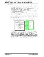
The debugger system can be configured to use standard ICSP communication for both
programming and debugging functions. This 6-pin connection is the same one used by
the older MPLAB ICD 2 In-Circuit Debugger.
The modular cable can be inserted into either:
• a matching socket at the target, where the target device is on the target board
(
), or
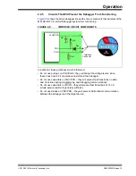
• a standard adapter/header board combo (available as a Processor Pak), which is
then plugged into the target board (
).
For more on standard communication, see
Appendix B. “Hardware Specification”
.
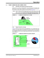
FIGURE 2-1:
STANDARD DEBUGGER SYSTEM – DEVICE WITH
ON-BOARD ICE CIRCUITRY
CAUTION
Communication Failure.
Do not connect the hardware before installing the software and
USB drivers.
CAUTION
Debugger or Target Damage.
Do not change hardware connections while the pod or target is
powered.
Note:
Older header boards used a 6-pin (RJ-11) modular connector instead of an
8-pin connector, so these headers may be connected directly to the
debugger.
Target Board
Target Device
or PIM
Power


