EVB-LAN9252-3PORT EtherCAT
®
ESC PHY Connection Mode User’s Guide
DS50002403A-page 20
2015 Microchip Technology Inc.
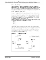
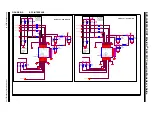
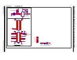
FIGURE 3-4:
SLAVE ADDRESS ALLOCATION
3.2.4
SPI + 3 Port Mode Selection
3.2.4.1
SPI
The SPI lines are directly connected to the SOC. No jumper settings are required for
SPI.
3.2.4.2
SPI/SQI/I
2
C AARDVARK
®
J11 & J12 connectors are used for Aardvark/SPI headers. Respective pin details are
given below in
. Resisters R61, R62 & R122 are need to be populated to use
this option. By default, R61, R62 & R122 are DNP.
3.2.4.3
3 PORT MODE
The following Assembly/jumper settings are used to configure LAN9252 in to 3-Port
mode.
3.2.4.3.1
Assembly of the Boards
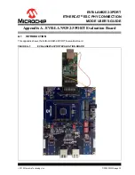
The MII Female Connector (J27) is used to connect External PHY Board.
EVB-LAN8740 MII PHY Board have been used as External PHY Board as shown in
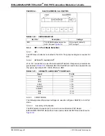
TABLE 3-12:
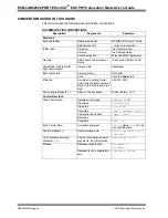
EEPROM SWITCH
Ref. Des
Description
Settings
SW3
I
2
C EEPROM Address selection
(A0,A1,A2) see
ON for logic 0 (default)
OFF for logic 1
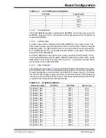
TABLE 3-13:
SPI/SQI/I
2
C AARDVARK
®
PIN DETAILS
Signal
Pin No
SCL
J11.1
SDA
J11.3
SCK
J11.7
SCS#
J11.9
SI(SIO0)
J11.8
SO(SIO1)
J11.5
SIO2
J12.3
SIO3
J12.4


