MICRO-EPSILON scanCONTROL 25 Series Assembly Instructions Manual Download Page 2

Page 2

scanCONTROL 25xx

4. 

Laser Safety

The scanCONTROL 25xx sensors operate with a semiconductor laser with a  
wavelength of 658 nm (visible/red). Operation of the laser is indicated visually by the 
LED on the sensor, see operating instructions Chap. 3.3.  
When operating the scanCONTROL 25xx sensors, the relevant regulations according to 
IEC 60825, Part 1 of 05/2014 and the applicable accident prevention regulations must 
be followed. The laser warning labels for Germany have already been attached. For 
other non German speaking countries, an IEC standard label is included in delivery and 
the versions valid for the user’s country must be attached before the device is put into 
operation for the first time.

  If both warning labels are covered over when the unit is installed, the user must 

ensure that supplementary labels are attached.
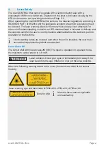
Laser Class 2M

The sensors fall within laser class 2M (IIM). The laser is operated on a pulsed mode, 
the 

maximum optical power is ≤ 8 mW. 

Laser radiation. Close your eyes or immediately turn away if the 
laser beam hits the eye. Irritation or injury of the eyes possible.

Attach the following warning labels to the cover (front and rear side) of the sensor 
housing.

LASER RADIATION

DO NOT STARE INTO BEAM

 OR EXPOSE USERS OF

CLASS 2M LASER PRODUCT

 TELESCOPE OPTICS

IEC 60825-1: 2014

P

≤ 8 mW; P

≤ 8 mW; H ≤ 52 W/m²; 

 

= 658nm; F = 0...4 kHz; t = 1 µs...∞

Laser warning sign and laser label LLT25xx-25, LLT25xx-50, LLT25xx-100

COMPLIES WITH 21 CFR 1040.10 AND 1040.11 

EXCEPT FOR CONFORMANCE WITH 

IEC 60825-1 ED. 3., AS DESCRIBED IN

LASER NOTICE NO. 56, DATED MAY 8, 2019

Only for USA

i

 Mark the laser area recognizable 

and everlasting.

Summary of Contents for scanCONTROL 25 Series

Page 1: ...xposure of sensor to aggressive media deter gents cooling emulsions Damage to or destruction of the sensor 2 Notes on CE Marking The following apply to the scanCONTROL 25xx measuring system EU Directi...

Page 2: ...th warning labels are covered over when the unit is installed the user must ensure that supplementary labels are attached Laser Class 2M The sensors fall within laser class 2M IIM The laser is operate...

Page 3: ...DESCRIBED IN LASER NOTICE NO 56 DATED MAY 8 2019 Only for USA Class 3B laser sensors are notifiable and a laser protection officer is required Mark the laser area recognizable and everlasting During o...

Page 4: ...urple Switching input In3 GND In3 7 Black Ground connection In3 Screen Housing Black Not electrically connected to GND 2 3 4 5 6 7 8 9 1 10 11 12 GND galvanically isolated from In1 In2 In3 RS422 Laser...

Page 5: ...cuit to switch off the laser With standard sensors connecting the supply voltage activates the laser light source in the sensor Wiring details are available in the operating instructions Chap 5 2 6 Et...

Page 6: ...Meaning Green Measurement is active Green flashes long Data transmission is active Green flashes short Controller is accessing laser Red flashes Error code 6 System Requirements scanCONTROL Configura...

Page 7: ...Close unused connection plugs with the included protective caps Turn on the power supply 24 VDC Please wait until the scanCONTROL measuring system is recognized by the PC This may take a few seconds N...

Page 8: ...Data Profile data of scanCONTROL can be accessed via GigEVision and GenICam for digital cameras via Ethernet interface SDK for fast integration into applications C C C and others Please refer to the r...

Page 9: ...or can be transmitted to a PLC via one of these fieldbus systems Furthermore all scanCONTROL sensor settings can be set via the 2D 3D Gateway e g Laser on off or User Mode Sensor parameterization Supp...

Page 10: ...2 5 3 0 5 7 LINK ACT MS I O ETHERNET NS 8 7 6 5 4 3 2 1 N O LINK ACT 1 2 X 1 X 2 8 1 ON 24V X3 0V 0 WBM 255 DHCP OU fieldbus coupler L1 L2 L3 N PE OU Filter module OU Fieldbus coupler 13 14 C D B A 75...

Page 11: ...al output terminals need a field supply of 5 VDC or 24 VDC depending on the module type After mounting the modules install the required wiring Connect the System supply out contacts of the OU Filter m...

Page 12: ...and free cable ends Calibration protocol assembly instructions 2 Protective caps 14 Additional Information Please refer to the enclosed online documentation the Status and Error Messages and Notes sec...

Reviews: