background image

Page 73

Appendix | Operating Menu

optoCONTROL 2600

A 5.4  Options (Interface)

3

1

5

1

0

RS232

Baud rate

1

5

1

1

9600 Baud

1

5

1

2

19200 Baud

1

5

1

3

38400 Baud

1

5

1

4

115200 Baud

1

5

2

0

RS232

parity

1

5

2

1

parity none

1

5

2

2

parity even

1

5

2

3

parity odd

1

5

3

0

RS232

stop bit

1

5

3

1

1

1

5

3

2

stop bit

2

4

1

6

1

0

RS422

Baud rate

1

6

1

1

9600 Baud

1

6

1

2

19200 Baud

1

6

1

3

38400 Baud

1

6

1

4

115200 Baud

1

6

2

0

RS422

parity

1

6

2

1

parity none

1

6

2

2

parity even

1

6

2

3

parity odd

1

6

3

0

RS422

stop bit

1

6

3

1

1

1

6

3

2

stop bit

2

1

6

1

5

691200 Baud

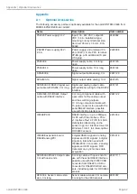
Fig. 68 Operating Menu 

Options (Interface)

The parameters which can be selected in the options are read out of the option data in the main memory and written 
back. The user can decide only on quitting the main menu whether the parameters are to be written into the flash 
memory. The data is then also present after 

Power ON

.

The option data located in the main memory is used for the measurement mode.
The currently set parameter appears first during selection.

Summary of Contents for ODC 2600-40

Page 1: ...101 73037 Göppingen Germany Tel 49 0 7161 98872 300 Fax 49 0 7161 98872 303 eltrotec micro epsilon com www micro epsilon com Your local contact www micro epsilon com contact worldwide ODC 2600 40 ODC 2600 40 209 Operating Instructions optoCONTROL 2600 ...

Page 2: ...Laser micrometer MICRO EPSILON Eltrotec GmbH Manfred Wörner Straße 101 73037 Göppingen Germany Tel 49 0 7161 98872 300 Fax 49 0 7161 98872 303 eltrotec micro epsilon com www micro epsilon com ...

Page 3: ...3 6 2 Menu Structure 23 6 3 Operation 24 6 3 1 Key Functions 24 6 3 2 Display 24 6 3 3 Main Menu 24 6 3 4 Adjustment with the Video Signal 25 6 3 5 Options 25 6 3 6 Select Measurement Program 26 6 3 7 Edit Measurement Program User specific Programs 28 6 3 7 1 Zero Setting Function 29 6 3 7 2 Mastering 30 6 3 7 3 Measurement Programs Segment and Multi Segment 30 6 3 7 4 Display Scaling 31 6 3 7 5 L...

Page 4: ...6 9 Show Software Version 61 7 Disclaimer 61 8 Service Repair 61 9 Decommissioning Disposal 61 Appendix A 1 Optional Accessories 62 A 2 Factory Setting 63 A 3 Other Pin Assignments 64 A 3 1 Cables for Analog Terminal Devices 64 A 3 2 Cable for RS232 and RS422 65 A 3 3 Interface Card IF2008 PCIE 66 A 4 Software Support with MEDAQlib 68 A 5 Operating Menu 69 A 5 1 Initialization and Operation in the...

Page 5: ...receiver or the controller Avoid damage scratches to the protective windows of the light source and receiver through unsuitable cleaning methods or cleaning solvents Inaccurate erroneous measuring values Do not touch the protective windows of light source and receiver with the fingers Wipe off any fingerprints immediately Inaccurate erroneous measuring values Avoid constant exposure of the measuri...

Page 6: ...ction class Light source receiver IP64 applies with connected cable Controller IP40 i The protection class is restricted to water no drilling emulsions cleaning solvents etc Avoid quick changes between hot and cold Use a protective housing if the effects of water are continuous The level of protection does not apply to the optical paths during operation because if they become contaminated the func...

Page 7: ...f the optoCONTROL 2600 is a high performance red LED LED light sources are not classified according to the laser standard On the controller a yellow LED Light On signals by its illumination that radiation is being emitted from the optical opening of the light source ...

Page 8: ...era in the receiver measures the projected outer contour of the target with high accuracy Light source Target Receiver Lens Lens Diaphragm LED red Filter CCD array Telecentric range Fig 1 Measuring principle 3 2 Structure of a Complete Measurement System A measurement system consists of light source receiver controller optoCONTROL consists of a sensor unit SU and a controller CU The sensor unit in...

Page 9: ...ssigned to the keypad see Fig 3 1 2 Up down movement in menus Value input 1 greater 2 smaller 3 Quitting a menu point change to the next higher hierarchical level 4 Entry into the selected menu point confirmation of entry By long press switches the input values are taken over Below the operating mode e g DIA EDGE A for absolute or R for relative measurement is displayed In the Multisegment operati...

Page 10: ...ap between two targets Distance between two selectable edges segment Serial measurement of up to four freely selectable segments multi segment via the digital output e g segments 1 4 and 2 3 i Factory setting Position edge bright dark Receiver Receiver Receiver Receiver 1 2 3 4 Fig 6 Methods of operation For each measurement program 2 limits and 2 warning levels can be programmed For the Multi seg...

Page 11: ... range Storage 20 C 70 C non condensing Operation 0 C 50 C non condensing Supply voltage 24 VDC 15 Max current consumption 1 A Shock DIN EN 60068 2 27 15 g 6 ms Vibration DIN EN 60068 2 6 2 g 20 500 Hz Protection class DIN EN 60529 Receiver Light source IP64 Controller IP40 Material Receiver Light source Aluminum housing Weight Light source 450 g Receiver 800 g Controller 1200 g Mounting rail 900 ...

Page 12: ...een entered the measurement is set to 00 000 during zero setting If the zero point input is activated for between 3 and 6 s closed resetting occurs to the measurement without mas ters or zeros Pulses which are shorter than 0 5 s or longer than 6 s are not processed The zero point input is only active in the normal measurement mode with valid measurements In the TRIGGER mea surement mode this input...

Page 13: ...d meaning that nothing has to be con nected to the 25 pole D Sub to put the system into operation i The activation of the input as light source control resets to normal operation The light source control has a maximum switching frequency of 10 Hz 3 12 Edge Detection Threshold for Transparent Measurement Objects The system s fixed edge detection threshold of the video signal across the entire mea s...

Page 14: ... edge detection threshold and carrying out a light comparison the measurement object can be detected by the sensor and the selected position or geometry then measured Edge of a transparent measurement object Dynamic edge detection threshold 75 Fig 11 Display image of the video signal with a dynamic threshold Measurement object Glass edge 0 5 mm thick 4 Delivery 4 1 Unpacking Included in Delivery 1...

Page 15: ...in the mounting rail For mounting either the supplied mounting screws or other suitable M4 screws should be used Please note the thread depth of 5 mm in both components To bolt on the individual components the three through holes of 4 8 mm dia in each component can also be used Mount the sensor only to the existing holes on a flat surface Clamps of any kind are not permitted Inaccurate erroneous m...

Page 16: ...00 5 7 87 20 1 Midrange 39 1 54 39 1 54 3 5 14 Measuring range 4 16 ø4 8 19 dia Mounting rail 50 1 97 100 3 94 1 1 100 3 94 80 3 15 24 94 71 2 80 35 1 38 35 1 38 40 1 57 40 5 1 59 71 2 80 45 1 77 12 47 26 5 1 04 3 0 1 18 Fig 13 Dimensional drawing of the sensor unit with mounting rail 1 Applies only for option 209 8 31 dia 4 5 18 dia 6 6 26 dia 11 43 dia 3K7 1 0 5 20 7 5 30 22 5 89 37 5 1 48 40 1 ...

Page 17: ...eely initially exact alignment of the housing edges with respect to one another should be ensured The housing edges must lie within one plane The angular deviation may be up to 0 25 For alignment try squares or rails are suitable aids Tolerances for maximum moving and tilting of the light source and receiver during installation and mounting The following illustrations show the permissible error ra...

Page 18: ...y attention to sufficient space for connectors and cables ESC 195 15 7 68 155 6 1 191 05 7 52 97 3 82 110 4 33 45 1 77 Ø4 6 18 dia Fig 17 Dimensional drawing controller Dimensions in mm inches i The light source and receiver are assigned to their particular controller through the serial number and must not to be endangered Minimum cable bending radius Signal output cable SCA2500 respectively SCD25...

Page 19: ...500 3 10 RS422 or SCD2500 3 3 RS232 see A 1 or your own screened cable When using the connecting cable SCA2500 x see A 1 the outer screen must be con nected to the receiver screen e g plug housing The inner screen acts as the signal return conductor analog ground AGND and must be connected to the receiver ground This screen should not have any connection to the housing screen plug housing When usi...

Page 20: ...erence potential for switching input 20 RS422 Receive negative Optocoupler input negative green Pin 1 HD SUB 15 1 7 RS422 Receive positive Optocoupler input positive yellow Pin 2 HD SUB 15 1 8 RS422 Send positive Serial output positive Imp brown Pin 4 HD SUB 15 1 21 RS422 Send negative Serial output negative Imp white Pin 3 HD SUB 15 1 9 RS232 Receive RxD Serial input RS232 green Pin 3 DB9F 2 22 R...

Page 21: ...e provided see circuit diagram The switching outputs are protected against overload and reverse connection i When connecting inductive loads e g relays always fit freewheel diodes across the load All GND signals are connected together internally and to the minus pole GND of the 24 V supply voltage Imax 100 mA 5R6 GND 24 VDC Last Controller Current monitoring Fig 21 Circuit diagram for switching ou...

Page 22: ...e GND of the 24 V supply voltage 3k3 GND 24 V I 7 mA Controller Fig 23 Basic circuit for switching inputs 5 8 Synchronal Signal Input The input is triggered by a further controller or another device Rext VHIGH VF ILED 100 Ohm ILED Example VHIGH 3 3 V ILED 15 mA VF 1 V Rext 53 3 Ohm also 56 Ohm All GND signals are connected together internally and with the minus pole GND of the 24 V supply voltage ...

Page 23: ...st Language Measurement unit mm or inch Error handling analog output Interface parameters active interface RS232 or RS422 External light control LED On Off Clear user data Video for adjustment light reference tuning and threshold adjustment Service menu Select measurement program Edge bright dark Edge dark bright Diameter width Gap Segment and multisegment User defined programs four max Edit measu...

Page 24: ...l measuring frequency but av eraged over 766 measurements display frequency about 3 Hz unless the number of averages is set higher than 766 To monitor all measurements the display can be selected to small with the key or Full Display Then MIN MAX and Peak to Peak P P can be observed at the full measuring frequency If the formation of the average was activated with 1 the display refers to the avera...

Page 25: ...ladjusted i If after a lengthy period of operation the video signal no longer reaches the maxi mum value it may be due to contamination In this case clean the protective windows with a lint free cloth and some alcohol isopropanol An optimum video signal see Fig 25 should be able to be obtained by appropriately moving and tilting the light source and receiver within the permitted tolerances see Fig...

Page 26: ...ee Fig 29 End of scan Edge 4 dark bright Edge 3 bright dark Edge 2 dark bright Edge1 bright dark Start of scan Receiver Edge bright dark Edge dark bright Fig 27 Definition of terms for measurement program edge End of scan Edge 4 dark bright Edge 3 bright dark Edge 2 dark bright Edge 1 bright dark Start of scan zero Receiver Segment 2 4 Segment 3 4 Gap Diameter Width Fig 28 Definition of terms for ...

Page 27: ...k edge and last dark bright edge Gap GAP Measurement between first dark bright edge and the following edge Segment SEG 2 4 Measurement between any 2 from a max of 80 selectable edges also possible from zero Multi segment MULTISEG Measurement of up to 4 selectable segments Serial output of measurements via the digital output No analog output 4 2 3 1 3 2 1 0 1 Segment 3 Segment 2 Segment 4 Segment 3...

Page 28: ...ined also after switch off Then you must save a user specific program under a new freely selected name This is then automati cally activated during switch on USER1 or the last user specified name used appears as a suggestion These can be overwritten so that the user specific program can be edited and saved again and again If you respond negatively with ESC to the query Measurement task store the c...

Page 29: ...ogram Zero setting leads to temporary offset values for the display and the analog output Pressing the ESC key again for 3 s clears the temporary offset values for the display and the analog output For this however a valid measurement must be located in the display not At this point the ESC key on being pressed for 3 s takes on as an exception a toggling function between normal absolute and zeroed...

Page 30: ... 00 000 With zero setting or mastering via the external input by joining the connections Signal 5 and GND 18 together there are two possibilities short pulse 0 5 to 3 s duration Zero setting or mastering when a valid measure ment is present and no master value is saved in the measurement program long pulse 3 0 to 6 s duration Resetting of the master or zero setting process Pulses which are shorter...

Page 31: ...he desired displacement to the displayed displace ment and enter the new value at Display offset In addition a two point calibration can be carried out For the two point calibration it is best to use two reference pieces which correspond to the smallest and largest expected measurements tl true measurement set value largest dimension ts true measurement set value smallest dimension dl Display valu...

Page 32: ...mit Higher limit 2nd segment LL Lower tolerance limit Lower limit 2nd segment Fig 31 Limit allocation Remark The limit output of the Multi segment measurement program differs from the other standard programs For the segment 1 2 one upper and one lower limit can be de fined 6 3 7 6 Averaging In the measurement system averaging can take place over a selectable number of consecutive measurements Here...

Page 33: ...ulse MIN CONT Peak to peak continuous Output of the P P value in continu ous measurement operation value is held until change or reset pulse occurs No evaluation of a trigger pulse P P CONT Maximum value triggered Output of the max value found between two trigger pulses corre sponds to sampling period The value is held on the output until the next trigger pulse or reset pulse MAX TRIG Minimum valu...

Page 34: ...options data no trigger mode can be set for the selected measurement program or a trigger mode already set is rendered ineffective and the NORMAL measure ment mode is set automatically The entered limits always relate to the measurement signal which is present after the trigger mode evaluation The trigger and reset pulses can also be controlled via the serial interface The NORMAL measurement mode ...

Page 35: ... Reset input Digital serial Error Processing time 2 1 ms Fig 36 Measurement mode example Maximum triggered t Trigger input Reset input Digital serial Internal measurment Meas 2 3 kHz 2 5 ms Processing time approx 1 ms Measurement Measurement at time of trigger pulse Error Meas 2 3 kHz Meas 2 3 kHz Fig 37 Measurement mode example Momantary value triggered ...

Page 36: ...nput In this respect the above formula is changed according to the analog gain Then it is possible for example to extend a measurement span of 10 mm to a voltage span of 10 V the analog gain in this case is 4 0 10 5 0 5 10 AF Analog gain AO Analog offset Output voltage in VDC 0 20 40 x in mm AF 1 AO 10 V AF 1 AO 0 V AF 2 AO 0 V AF 1 AO 5 V AF 2 AO 10 V AF 4 AO 25 V Fig 38 Analog scaling of output ...

Page 37: ...lid measurement is retained or the voltage 10 04 VDC is output This option is then also valid for the display i e either the last valid measurement or is displayed 6 5 Synchronization of optoCONTROLs Connect the synchronizing signal output Signal of controller 1 with the synchro nizing signal input Signal of controller 2 and proceed similarly with the minus pole Further systems can be added by cas...

Page 38: ...2 Picture 2 1 SYNCOUT Master 4 600 Hz SYNCOUT Slave 4 600 Hz approx 12 µs Fig 40 Time offset through synchronizing signal 1 2 3 4 5 Internal cycle signal Synchron OUT Data Fig 41 Time response controller 1 Integration 2 Reading 3 Computation 4 Controlling 5 Output ...

Page 39: ... bits parity selectable 1 or 2 stop bits adjustable via menu Se lect RS232 parameter standard 8 N 2 RS422 Baud rate 9 6 to 691 2 kBaud selectable via menu RS422 baud rate Data format 8 data bits parity selectable 1 or 2 stop bits adjustable via menu Se lect RS422 parameter standard 8 N 1 6 6 2 Serial Measurement Output The serial output format of the measurement can be set in the options data menu...

Page 40: ...e DW The following formula is used for the conversion of the digital values DV to the measurement values MV in mm MV mm DV 40 824 65519 0 4204872 The settings Offset and Gain for the display or the analog output have no effect on the digital value With errors a digital value of 65520 is output Error messages during measurement output 65521 No edge 65522 At the beginning of the picture 65523 At the...

Page 41: ...es a command it is answered in that the command is returned with the MSB in Byte 2 set to 1 If the sensor finds an error in executing the command the second highest bit in Byte 2 is also set to 1 When the sensor responds to a com mand no header is sent i The controller processes the data in the Little Endian Format Example The 32 bit command word INFO 0x0000 2011 has two contents First part 0x2011...

Page 42: ...t pro gram data to the main memory 0x00002029 SAVE OPT RAM TO FLASH Save the option data from the main memory to the flash memory 0x0000202A SAVE MPR RAM TO FLASH Save the measurement pro gram data from the main mem ory to the flash memory 0x0000202B TRIGGERMODE RESET In the measurement mode Trigger mode reset active reset of the output values 0x0000202C TRIGGERMODE TRIGGER In the measurement mode...

Page 43: ...0xA0 0x10 0x00 0x0010A011 without error ArticleNumber 98765432 ASCII 8 Byte SerialNumber 1234567 ASCII 8 Byte Option 000 ASCII 8 Byte Measurement range mm 40 Binär 0x28000000 Reserve Binär 0xDE83EB3D SoftArtBoot Std ASCII 4 Byte SoftArtArm Std ASCII 4 Byte SoftArtDSP Std ASCII 4 Byte SoftVersionBoot 1003 Binär 0xEB030000 SoftVersionARM 1006 Binär 0xEE030000 SoftVersionDSP 1002 Binär 0xEA030000 6 6...

Page 44: ...0000 Error code i Start is on when the sensor is switched on The command Stop is volatile and is lost when the voltage supply is switched off or the Reset command is sent 6 6 3 4 Reset Command Name RESET Description The sensor executes a software reset This corresponds to switch ing the sensor off and then on again Command Byte 1 Byte 2 Byte 3 Byte 4 hex 0x0D 0x0D2B2B2B 0 D C 1 0x3143444F 0x01 0x2...

Page 45: ...sor off and on the last saved measurement program is loaded Command Byte 1 Byte 2 Byte 3 Byte 4 hex Remark 0x0D 0x0D2B2B2B 0 D C 1 0x3143444F 0x23 0x20 0x01 0x00 0x00012023 Command follow ing lenght 32 bit words 0x02 0x00 0x00 0x00 0x00000002 0 EDGEHL 1 EDGELH 2 DIA 3 GAP 4 SEG 2 4 5 MULTISEG 6 USER1 7 USER2 8 USER3 9 USER4 Response Byte 1 Byte 2 Byte 3 Byte 4 hex Remark 0 D C 1 0x3143444F 0x23 0x...

Page 46: ...2 0x04 0x00 0x00 0x00000402 Front edge Segment 3 2 Segment 4 4 0x08 0x06 0x00 0x00 0x00000608 Rear edge Segment 3 8 Segment 4 6 Response Byte 1 Byte 2 Byte 3 Byte 4 hex Remark 0 D C 1 0x3143444F 0x24 0xA0 0x03 0x00 0x0003A024 Without error 0x00 0x00 0x00 0x00 0x00000000 Error code 6 6 3 7 Read out min max Values Name RD MINMAX Description After the command response the min max values are transmitt...

Page 47: ...in max content is set to zero Command Byte 1 Byte 2 Byte 3 Byte 4 hex 0x0D 0x0D2B2B2B 0 D C 1 0x3143444F 0x34 0x20 0x00 0x00 0x00002034 Response Byte 1 Byte 2 Byte 3 Byte 4 hex Remark 0 D C 1 0x3143444F 0x34 0xA0 0x04 0x00 0x0004A034 Without error 0x34 0xE0 0x03 0x00 0x0003E034 Error 4 bytes error code Min 0 65519 Binär 0x00008B3E Max 0 65519 Binär 0x00008B4B Min Max mm Min Max 0 65519 40 824 6551...

Page 48: ...ry 0x0032 50 Thresshold value for dark light transition Contrast Binary 0x3232 50 50 Reserve 2 Binary 0x0000 Active interface Binary 0x0001 RS232 RS232 Baud rate Binary 0x0001C200 115200 Bd RS232 Parity Binary 0x0000 None RS232 Stop bits Binary 0x0002 2 RS232 TimeOut Transmit Binary 0x0001 No effect RS232 TimeOUT Receive Binary 0x0001 No effect RS422 Baud rate Binary 0x000A8C00 691200 Bd RS422 Par...

Page 49: ... source Binary unsigned short 16 0 1 0 not active 1 active Light intensity Binary unsigned short 16 No effect The factory data are accept ed Threshold value for dark light transition Binary unsigned short 8 20 90 20 90 Contrast Binary unsigned short 8 0 100 0 100 Reserve 2 Binary unsigned short 16 Active serial interface Binary unsigned short 16 0 1 0 RS422 1 RS232 RS232 Baud rate Binary integer 3...

Page 50: ...orrect measurument program number Avoid error Data are not accepted 6 6 3 11 Save Option Data Name SAVE OPT RAM TO FLASH Description With this command the currently valid option data is written from the main memory to the flash memory Command Byte 1 Byte 2 Byte 3 Byte 4 hex 0x0D 0x0D2B2B2B 0 D C 1 0x3143444F 0x29 0x20 0x00 0x00 0x00002029 Response Byte 1 Byte 2 Byte 3 Byte 4 hex Remark 0 D C 1 0x3...

Page 51: ...inary 0x00000000 0 0 mm Display gain Binary 0x3F800000 1 0 Upper limit Binary 0x42200000 40 0 mm Lower limit Binary 0x00000000 0 0 mm Upper warning Binary 0x42200000 40 0 mm Lower warning Binary 0x00000000 0 0 mm Reserve 1 Binary 0x0000 Measurement mode Binary 0x0000 NORMAL Median Binary 0x0003 over 3 values Number of averages Binary 0x0001 1 Reserve 2 Binary 0x0000 Measurement program Binary 0x00...

Page 52: ...SER4 Measurement program name ASCII char 8x8 A Z 0 9 Only uppercase letters The last space characters are deleted Space characters be tween the letters are replaced by underscore Place holder Binary unsigned short 16 Analog offset Binary float 32 10 000 10 000 Entry is made in VDC Analog gain Binary float 32 4 0000 4 0000 Display offset Binary float 32 99 999 99 999 Entry is made in mm Display gai...

Page 53: ...y unsigned short Low Byte High Byte 16 0 80 0 80 Example front edge 1 Seg 2 front edge 2 Seg 4 0x0402 hex 1026 decimal Front edge Segment 3 4 Binary unsigned short 16 0 80 0 80 Reserve Binary unsigned short 16 Reserve Binary unsigned short 16 Rear edge Segment 1 2 1 Segment 2 Segment Binary unsigned short Low Byte High Byte 16 0 80 0 80 Example rear edge 1 Seg 8 rear edge 2 Seg 7 0x0807 hex 1800 d...

Page 54: ...yte 4 hex 0x0D 0x0D2B2B2B 0 D C 1 0x3143444F 0x2A 0x20 0x00 0x00 0x0000202A Response Byte 1 Byte 2 Byte 3 Byte 4 hex Remark 0 D C 1 0x3143444F 0x2A 0xA0 0x03 0x00 0x0003A02A Without error 0x00 0x00 0x00 0x00 0x00000000 Error code Possible errors 0x00000006 Flash access error 6 6 3 15 Resetting the Output Values in the Trigger Measurement Mode Name TRIGGERMODE RESET Description Resets the output va...

Page 55: ...44F 0x2C 0xA0 0x03 0x00 0x0003A02C Without error 0x00 0x00 0x00 0x00 0x00000000 Error code 6 6 3 17 Activating the Light Reference Tuning Name SET LIGHT REFERENCE TUNING Description Activates the output in the trigger measurement mode Command Byte 1 Byte 2 Byte 3 Byte 4 hex 0x0D 0x0D2B2B2B 0 D C 1 0x3143444F 0x2D 0x20 0x00 0x00 0x0000202D i This command corresponds to the menu 1B20 Light reference...

Page 56: ...4F 0x2E 0xA0 0x03 0x00 0x0003A02E Without error 0x00 0x00 0x00 0x00 0x00000000 Error code 6 6 4 Error Responses 0x04 Too much data received 0x06 Flash access error 0x0a Error on writing to the RAM 0x0b Incorrect data transmitted see Valid values 0x0c Incorrect measurement program number 0x01 Error destination if μC has to send information or data an error message is returned e g passing data to th...

Page 57: ...tion of limit switching functions Each cycle takes about 435 μs 1 measuring rate After 5 cycles in each case the measured value N is available on the output The delay between the input reaction and output signal is 2175 μs The processing of the cycles occurs sequentially in time and parallel in space see Fig 52 After a further 435 μs the next measurement N 1 is pres ent on the output One output cy...

Page 58: ...5 0 1 0 15 0 2 0 25 0 3 0 35 0 4 0 45 mm 0 3 mm Edge measurement Region with measurement errors approx 0 05 mm wide Fig 53 Effects on the light beam due to edge changes 6 8 2 Extraneous Light The telecentric objective lens in the receiver only allows beams onto the CCD array which are precisely parallel to the optical axis Such a beam can be generated by a self illuminated measurement object or by...

Page 59: ... ambient conditions free of dust and oil 6 8 4 Transparent Target Objects i With application on transparent materials e g edges of clear films and plates or transparent round material glass tubes MICRO EPSILON Eltrotec GmbH recom mends that tests are first carried out Use the menu Video see A 5 3 It is likely that transparent target objects e g glass rods or tubes shade the light beam at the outer...

Page 60: ...ollowing pictures show three possible states Video signal is ok delivery status Fixed threshold for edge detection Video signal to low cuts almost the fixed edge detection threshold Increase the light intensity Video signal too high Decrease light intensity Fig 54 Different states of the video signal The following steps are recommended 1 Exit the menu Video Press the key ESC 2 Press the arrow key ...

Page 61: ...LON is exclusively responsible for repairs It is not permitted to make unauthorized structural and or technical modifications or alterations to the product In the interest of further development MICRO EPSILON reserves the right to modify the design In addition the General Terms of Business of MICRO EPSILON shall apply which can be accessed under Legal details Micro Epsilon https www micro epsilon ...

Page 62: ...ith RS422 interface 3 m long component cable with open ends for the analog output and the switching outputs 10 m long component cable with 15 pole connector for use with the serial RS422 interface possible use with IF2004 interface card 2901122 IF2008 PCIE RS422 interface up to 4 MBaud for PC with PCIe interface PCIe x1 interface Rev1 0 FIFO for 4096 data bytes depending on the sensor log incl int...

Page 63: ...ion with 15 pole plug to be used with IF2008 PCIE card 2901561 SCD2500 8 IF2008 interface cable Output cable 8 m long in addition with 15 pole plug to be used with IF2008 PCIE card via RS422 2901563 SCD2500 3 CSP Connection cable 3 m long with straight plugs for an ODC2500 or ODC2600 mi crometer to the CSP2008 universal controller 2901504 SCD2500 10 CSP Connection cable for an optical ODC2500 35 o...

Page 64: ... output open collector red blue 25 Analog output AGND Reference potential for analog signal Inner shield thin cable 13 Analog output Signal Analog signal voltage green Fig 55 Pin assignment standard analog output cable Pin Signal Signal type or connector type Core color in the sig nal and output cable CA2500 x 01 1 Error output signal Switching output red 14 Error output GND Switching output blue ...

Page 65: ...13 Analog output signal green black outer shield on 25 pin connector housing Fig 57 SCD2500 x 3 RS232 pin assignment 25 pin Signal 15 pin Braids 1 Error output signal red 14 Error output GND blue 2 Upper tolerance limit signal purple 15 Upper lower tolerance GND black and brown 3 Lower tolerance limit signal white 16 Upper warning limit signal pink 4 Upper lower warning limit GND gray and gray pin...

Page 66: ... must be set to the active RS422 interface and the following default settings Baud rate 691200 Baud Data format 8 data bits no parity 1 stop bit 8 N 1 i IF2008 PCIE requires an X7 supply via PC Fig 59 View IF2008 PCIE Turn on downstream computers first and then the controller All inputs are isolated via optocouplers on the ODC 2600 controller as well as on the IF2008 PCIE interface card The design...

Page 67: ...ubminiature connector view on solder pin side of cable connector 25 pin Sub D Signal 15 pin Sub D Braids 1 Error output Signal red 14 Error output GND blue 2 Upper tolerance limit signal purple 15 Upper lower tolerance limit GND black and brown 3 Lower tolerance limit signal white 16 Upper warning limit signal pink 4 Upper lower warning limit GND gray and gray pink 17 Lower warning limit signal re...

Page 68: ...otocol to communicate with the individual sensors The individual commands and parameters for the sensor to be addressed will be set with abstract functions MEDAQLib translates the abstract functions in compre hensible instructions for the sensor MEDAQLib contains a DLL which can be imported into C C VB Delphi and many additional programs makes data conversion for you works independent of the used ...

Page 69: ...switching Temporary mastering zero setting 2nd switching Undo of mastering zero setting Main menu ESC ESC ESC Display change Press briefly Press for 3 seconds Press briefly No Yes Yes No Load the option and measurement program data into the main memory Multi segment measurement program MULTISEG A S1 mm NORMAL P P Min Max 0 028 21 0041 MULTISEG A S2 mm NORMAL P P Min Max 0 0083 11 5582 11 5665 11 5...

Page 70: ... USER1 Save measurement program and option data in the flash this data is present at Pow er On Software reset Has the option data changed Flash not same as main memory 0 0 0 0 Option store Yes ENTER No ESC No Yes Current data in the main memory is used Yes No ESC ESC Briefly one place further Press for 3 seconds ESC Current data in the main memory is used Save measurement program and option data i...

Page 71: ...lue in main memory ESC 1 2 1 0 Menu language german 1 2 2 0 Menu language english 1 3 0 0 select dimension for displayed reading 1 3 1 0 reading mm 1 3 2 0 reading inch 1 4 0 0 error handling reading analog output 1 4 1 0 hold last valid reading 1 4 2 0 Error i e 10 04 V DC is output 1 5 0 0 select RS232 parameter 1 6 0 0 select RS422 parameter ESC 1 3 4 2 Fig 66 Operating Menu Options General Set...

Page 72: ...output format of the measured value 1 8 0 0 select external toggling the light source 1 9 0 0 clear user data options program 1 A 0 0 video 1 B 0 0 service menu 1 C 0 0 RS422 1 7 1 0 RS232 1 7 2 0 binary 1 8 1 0 ASCII 1 8 2 0 not activ 1 9 1 0 activ 1 3 2 0 Clear data Are you sure Yes ENTER No ESC 1 A 1 0 9 Fig 67 Operating Menu Options General Settings part 2 ...

Page 73: ...ud 1 6 2 0 RS422 parity 1 6 2 1 parity none 1 6 2 2 parity even 1 6 2 3 parity odd 1 6 3 0 RS422 stop bit 1 6 3 1 1 1 6 3 2 stop bit 2 1 6 1 5 691200 Baud Fig 68 Operating Menu Options Interface The parameters which can be selected in the options are read out of the option data in the main memory and written back The user can decide only on quitting the main menu whether the parameters are to be w...

Page 74: ...1 B 3 1 reset light referencing tuning successfully 1 B 2 1 error beam path not freely press return 1 B 1 0 9 Art Vers Boot STD 1004 ARM STD 1014 DSP TLZ 1016 1 C 3 1 Error X active UW not active OW not active UT X active OT X active 1 C 3 0 Test switching output Only activation with temporary 1 C 2 1 1 C 2 0 Adjustment illumination Intensity in percent 70 1 C 1 1 1 C 1 0 Software version Only dis...

Page 75: ...sh the Enter button 2 0 0 0 Select measurement program ESC Push the ESC button 1 0 0 0 Main menu ESC 0 0 0 0 Save option Yes Enter No ESC Push the Enter button to save the settings Example to select a measurement program Fig 70 Operating Selecting the Measurement Program The parameters which can be selected in the options are read out of the option data in the main memory and written back The user...

Page 76: ... program press for 3 sec press briefly forone place further enteroffset fordisplay enter factor for display enter offset for analog output enter factor for analog output enter upper warning limit displayoffset 00 0000mm displaygain 1 0000 analogoffset 00 0000VDC analoggain 1 0000 highwarning HW 040 0000mm Fig 71 Operating menu Editing the Measurement Program 1 These menu points cannot be selected ...

Page 77: ... enter average for reading 3 C 1 0 averaging sliding 1 128 recursive 129 4096 0001 3 D 0 0 enter measuring mode 3 D 1 0 measuring mode NORMAL choice MAX_CONT MIN_CONT P P_CONT MAX_TRIG MIN_TRIG P P_TRIG SC1_TRIG 2 2 2 choice 3 5 7 9 Fig 72 Operating menu Editing the Measurement Program part 2 i The measuring mode cannot be voted for respect if light control is active Measuring mode NORMAL 2 The li...

Page 78: ...dge pr No Yes Error trailing edge No Of edges press return worked on segment number of segments to be measured No Yes detected edges 6 1 segment 1st edge 1 3 1 2 0 detected edges 6 1 Segment 1st edge 1 2nd edge 2 3 1 2 0 back to menu 3100 worked on segment 1 Fig 73 Operating menu Editing the Measurement Program part 3 The leading edge can also be set 0 then the measurement is taken from the zero p...

Page 79: ...er limit 1 st segment Lower warning level Lower limit 1 st segment Higher tolerance limit Higher limit 2 nd segment Lower tolerance limit Lower limit 2 nd segment 3 7 0 0 enter 1 segment high limit 3 7 1 0 high limit S1 HW 040 0000 mm 3 8 0 0 enter 1 segment low limit 3 8 1 0 low limit S1 LW 000 0000 mm 3 9 0 0 enter 2 segment high limit 3 9 1 0 high limit S2 HL 040 0000 mm 3 A 0 0 enter 2 segment...

Page 80: ...lay offset 000 0000 mm 000 0000 mm 000 0000 mm 000 0000 mm 000 0000 mm 000 0000 mm Display gain 1000 1000 1000 1000 1000 1000 Analog offset 00 000 VDC 00 000 VDC 00 000 VDC 00 000 VDC 00 000 VDC 00 000 VDC Analog gain 1000 1000 1000 1000 1000 1000 Higher warning level higher WL 1st segm 040 0000 mm 040 0000 mm 040 0000 mm 040 0000 mm 040 0000 mm 040 0000 mm Lower warning level lower WL 1st segm 00...

Page 81: ......

Page 82: ...ner Straße 101 73037 Göppingen Germany Tel 49 0 7161 98872 300 Fax 49 0 7161 98872 303 eltrotec micro epsilon com www micro epsilon com Your local contact www micro epsilon com contact worldwide X9751125 B062101HDR MICRO EPSILON MESSTECHNIK ...

Reviews: