Page 57
Measure
optoCONTROL 2600
6.7
Timing
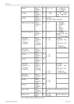
The controller in the ODC 2600 operates internally in 5 cycles:
1. Integration: Gathering of the incoming light in the receiver (measurement).
2. Reading in: Conversion and saving of the light signals as digital values.
3. Computation: Measurement determination in the DSP (digital signal processor).
4. Controlling: Transfer of the measurements to the output controller where statistical
computations (Segment, Min, Max, PtP, Limits, Zero-setting)
5. Output:
Output via the analog and digital interfaces, activation of limit switching
functions.
Each cycle takes about 435 µs (1 / measuring rate). After 5 cycles in each case the
measured value N is available on the output. The delay between the input reaction and
output signal is 2175 µs. The processing of the cycles occurs sequentially in time and
parallel in space
. After a further 435 µs the next measurement N + 1 is pres-
ent on the output.
One output cycle is added for each segment in
Multi-segment
mode. This reduces
the measuring rate.
Cycle
1.
2.
3.
4.
5.
Time (µs)
Integration
(measurement)
N
N+1
N+2
N+3
N+4
435
Reading in
N-1
N
N+1
N+2
N+3
870
Computation
N-2
N-1
N
N+1
N+2
1305
Controlling
N-3
N-2
N-1
N
N+1
1740
Output
N-4
N-3
N-2
N-1
N
2175
Fig. 52 Internal cycles in the ODC controller
Summary of Contents for ODC 2600-40
Page 81: ......


