


Page 35
Electrical Installation
thermoMETER CT
7.3
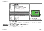
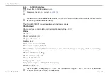
Cable Assembling
The cable gland M12x1.5 of the controller allows the use of cables with an outer diameter of 3 to 5 mm.
Remove the isolation from the cable (40 mm power supply, 50 mm signal outputs, 60 mm functional
inputs).
Cut the shield down to approximately 5 mm and spread the strands out.
Extract about 4 mm of the wire isolation and tin the wire ends.
Place the pressing screw, the rubber washer and the metal washers of the cable gland one after the
other onto the prepared cable end
Spread the strands and fix the shield between two of the metal washers.
Insert the cable into the cable gland until the limit stop.
Screw the cap tight.
Every single wire may be connected to the appropriate screw clamps according to their colors.
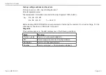
Pressing screw
Shield
Metal washer
Rubber washer
Fig. 9 Cable assembling
i
Use shielded cables only!
The sensor shield has to be grounded!


