Micrel SY87729L Manual Download Page 6

6

SY87729/39L

 Evaluation Board

Micrel, Inc.

M9999-071906
[email protected] or (408) 955-1690

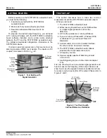
Figure 11. Desired Output Frequency Cannot Be

Synthesized

The error message is telling you that SY87729/39L cannot

synthesize an 8.9MHz clock from a 27MHz clock.
Remember, the smallest output frequency SY87729/39L can
generate is 9.0MHz, no matter what the input frequency is.

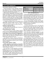
Let’s try another example. Suppose we want to generate

111,100,000MHz from 27MHz. Hit the “Tab” key until the
output frequency value is highlighted, and then type “1”,
“1”,  “1”,  “.”,  “1”, and “m”. Your calculation module should
look like that in Figure 12.

Figure 12.  Generating 111.1MHz With the Wrapper

The status line begins with the word SUCCESS. This

means that SY87729/39L can generate the output frequency
specified. The closest frequency it can generate is shown
in the “Actual” box.  In this case, it is 111,099,130MHz, just
a bit low. The status line shows that the actual output
frequency differs from the desired (or target) output
frequency by 8ppm in frequency.

On the far right, the six SY87729/39L configuration

parameters to generate this output frequency are shown.
These parameters could be used by a firmware engineer to
program an embedded processor to configure
SY87729/39L.

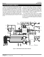
In the above example, the wrapper synthesizer is used

to obtain the best possible actual output frequency. If the
wrapper synthesizer is not used, the calculation module
should look like that in Figure 13.

Figure 13. Generating 111.1MHz Without the Wrapper

Note that in this example, the “M” and “N” configuration

parameters are both 14. This means that the wrapper
synthesizer is passing the frequency of the fractional-N
synthesizer unchanged. Because of this, the nearest
frequency is now 111,103,448Hz, just a bit higher than the
target frequency. The status line indicates that the frequency
error is now 32ppm, which is not as good as the 8ppm error
when the wrapper synthesizer is used.

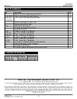
Let’s try another example. Let’s generate an OC-12 clock

from this 27MHz input frequency. The calculation module
should look like that shown in Figure 14. Note that, since
the wrapper synthesizer was reserved, both the “M” and the
“N” configuration parameters are set to 14.

Figure 14. Generating 622.08MHz Without the Wrapper

(Using SY87739L only)

Now let’s see what happens when you use the wrapper

synthesizer. Your calculation module should look like that
in Figure 15.

Summary of Contents for SY87729L

Page 1: ...rinter cable parallel to centronics user supplied Rev B Amendment 0 Issue Date July 2006 The SY87729 39L are rate independent fractional N frequency synthesizer ICs From a single reference source they...

Page 2: ...ength matched one foot SMA cables or a digital signal generator such as the HP8133A 3 A PC with a parallel port running Windows 4 If you are running Windows NT Windows 2000 or Windows XP you will need...

Page 3: ...oads on the default parallel port LPT1 You may instead decide to allow downloads only on LPT2 if your computer is equipped with a second parallel port or you may also decide to allow two SY87729 39L E...

Page 4: ...ng only LPT2 the Direct IO control panel should look like Figure 6 Figure 6 Correct I O Addresses for LPT2 Access Finally to access both LPT1 and LPT2 the Direct IO control panel should look like Figu...

Page 5: ...zer should be used That is why the calculation module starts with the Use radio button selected in the Wrapper group box This tells the calculation module to use the wrapper synthesizer if there is so...

Page 6: ...s output frequency are shown These parameters could be used by a firmware engineer to program an embedded processor to configure SY87729 39L In the above example the wrapper synthesizer is used to obt...

Page 7: ...he download application Next the configuration parameters are entered Lastly the configuration is downloaded and it is verified that no errors in the configuration parameters have occurred The first s...

Page 8: ...ly take on a value between 17 and 32 inclusive PostDiv 1 16 18 20 The value in the PostDiv configuration edit box may only be one of the values 22 24 26 28 30 32 36 listed 40 44 48 52 56 60 MDIV 15 18...

Page 9: ...enced to VCC so the voltage to set the signal generator to depends on the value of VCC For a VCC of 3 3V the high level of the clock signal should be between 2 135V and 2 42V The low level of the cloc...

Page 10: ...nd have the calculation module determine the configuration parameters Have the download module configure the SY87729 39L evaluation board and verify that the indicator at the upper right of the downlo...

Page 11: ...interface pin 11 This is how the applications software determines whether or not an SY87729 39L evaluation board is attached to the parallel port 1 9 10 11 12 13 14 15 16 1 2 3 4 5 6 7 8 24 23 22 21...

Page 12: ...uation Board Part IC Package Operating Range SY87729L EVAL EPAD TQFP 32 40 C to 85 C SY87739L EVAL EPAD TQFP 32 40 C to 85 C MICREL INC 2180 FORTUNE DRIVE SAN JOSE CA 95131 USA TEL 1 408 944 0800 FAX...

Reviews: