


Instruction Manual MIC type EC-912
Revision no.4
30 / 38
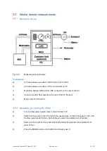
Electrical leakage
The leakage current in the MIC can be checked by dismounting the holder for the radioactive source
as described in Section 5.1.1 and following the below procedure:
a)
Press the MCU MODE button to indicate mode Uc and adjust the Uc trimmer on the
MCU until the display reads 25.0.
b)
Press the MCU MODE button to indicated mode X.
c)
Press the MCU CAL button. The CAL ON indicator shall light up.
d)
Adjust the Offset trimmer on the MCU until the display reads 1.00.
e)
Press the MCU CAL button. The CAL ON indicator shall extinguish
f)
Notice the display reading XLEAK.
The leakage current in the MIC is:
ILEAK = 100 • (1.00—XLEAK) [pA]
The leakage current in the MIC should be less than 1 pA. If the leakage current in the MIC is greater
than 1 pA the electrode assembly is probably covered with smoke de-posits and needs cleaning.
Refer to Section 5.1.1 for cleaning of ionization chamber.
Spare parts
The following spare parts can be ordered separately:
Type:
Designation
EC-999-01
Air filters for flow control unit (20 pcs)
EC-999-08
Vacuum pump VTE 3 complete with adjusted reduction valve
EC-999-09
PVC hose, 15m standard
EC-999-10
MIC cable, 10m standard (other lengths upon request)
EC-999-12
Maintenance kit for vacuum pump (1 filter, 2 sealings, 4 blades)
EC-999-13
Set of O-rings for Flow Control Unit
EC-999-40
Flow Control Unit complete with air filter
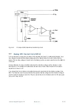
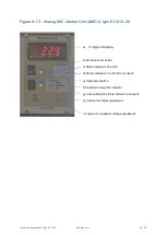
EC-912-20
Analog MIC Control Unit (AMCU)
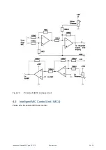
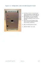
EC-912-25
Intelligent MIC Control Unit (IMCU)