04.
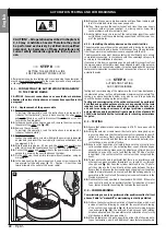
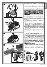
Attach the motor connector again (phase 4) and complete insertion of
the battery and control unit.
05.
Lastly, refit the cable ducting support and the lower cover of the gear-
motor.
For further information on the battery, refer to its specific instruction manual.
A.5 - Connecting the solar power supply system (PF)
The “WT”system can operate also with the PF solar power supply system.
Special technical provisions have been envisaged to minimise energy
consumption when the automation is stationary, by turning off all devices
not essential to operation (for example photocells and the key-operated
selector light). In this way all energy available and stored in the battery is
used to move the gate.
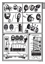
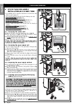
To connect the PF to the “WT” control unit, refer to
fig. 36
and the follow-
ing procedure.
01.
Remove the control unit from its seat as described in paragraph A.1.
02.
Disconnect the automation from the power mains and remove the
PR2 backup battery (if fitted).
CAUTION! - When the automation
is powered by “PF”, it cannot and MUST NEVER BE POW-
ERED at the same time by the mains or the PR2 backup
battery (if fitted).
03.
Connect the adaptor cable (supplied with the PF kit) to the socket on
the control unit, taking care to observe polarity (refer to the cable
instruction leaflet.
Caution
! – the cable connector can only be insert-
ed in one direction).
04.
Lastly, insert the control unit in its seat, refit the cable ducting support
and refit the lower cover of the gearmotor.
For further information on the PF device, refer to its specific instruction
manual.
A.5.1 - PF application limits
: maximum possible number of
cycles per day within a set period of the year
The PF photovoltaic power supply enables the automation to operate
completely autonomously for a limited number of manoeuvres per day, i.e.
for as long as the energy generated by the photovoltaic panel and stored
in the battery remains above the level of consumption with gate manoeu-
vres. A simple calculation enables an estimate of the maximum number of
cycles per day (1 cycle = o closing) performed by the automation
in a certain period of the year, provided that a positive energy balance is
maintained.
The first step in
calculating the energy available,
is dealt with in the PF
instruction manual; the second step in
calculating the energy con-
sumed
and therefore the maximum number of cycles per day, is dealt
with in this paragraph.
• Calculating the energy available
To calculate the energy available, proceed as follows (refer also to the PF
instruction manual):
01.
On the terrestrial map supplied in the PF kit instruction manual, locate
the point of system installation; then read the value
Ea
and the
degrees of
latitude
of this location
(E.g. Ea = 14; degree = 45°N)
.
CAUTION!
- The PR2 battery is an optional device
that enables the automation to run exclusively on
solar power. If this is envisaged in the automation,
the device must be connected to the control unit
only after completing all the other tasks described
in this manual.
34
35
2
1
33
36
English
English –
25
Summary of Contents for WT1S
Page 11: ...1 2 3 4 45 3 1 2 a c b OK b a a b c d b a 5 6 7 8 9 10 11 12 13 13 English 10 English...
Page 14: ...OK b a 1 2 17 AA ok BB no OK 18 1 2 16 3 4 2 1 English English 13...
Page 15: ...b a 1 2 3 4 5 6 20 a b 1 2 3 4 19 English 14 English...
Page 36: ...Technical Documentation English English 35...
Page 37: ...English 36 English...
Page 39: ...English 38...
Page 41: ...English 40 English...
Page 44: ...Goniometer English English 43...
Page 45: ...44 English English Goniometer...


