Meyers Manx Kick-Out SS Build Instruction Manual Download Page 14


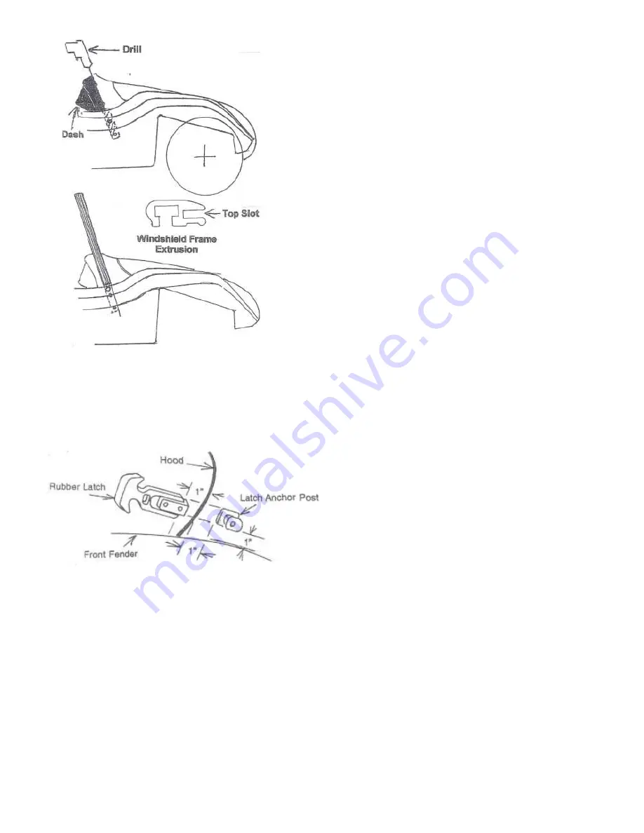
Step #12 – Dashboard Assy – Part #K-234


Lifting  the  cowl  up  slightly,  the  dash  is  fitted 
under the top edge of the cowl.  The ends of 
the  dash  will  reach  around  the  ends  of  the 
dash  frame  to  butt  the  ends  of  the  cowl  at 
the dash frames centerline.  Using the 7 holes 
in the cowl as a guide, drill down through the 
dash  which  is  just  below.    Using  the  seven 
10/32”  x  1”  long  bolts,  nuts  and  washers, 
secure  the  top  of  the  dash  and  cowl  to  the 
dash  frame.    The  three  ¼  /20”  bolts  are 
temporarily  removed  at  the  bottom  of  the 
dash  frame  to  drill  and  reassemble  the 
bottom of the dash. 
 

Step #13 – Windshield Assy – Part #K-255


With  the  small  top  slot  facing  forward  on  the 
windshield  frame,  the  two  6”  long  bars  with 
studs attached must be trial fitted.  That is, slid 
up  into  the  open  ends  of  the  windshield 
frame.    Once  satisfied  as  to  their  final 
positioning,  with  drill,  clean  out  any  fiberglass 
obstructions  in  the  four  holes  at  the  cowl 
ends.    Carefully  transfer  from  windshield,  the 
bars  to  the  awaiting  holes  at  the  cowl  ends.  
Loosely  attached,  you  and  a  helper  should 
lower  the  windshield  down  onto  its  new 
home,  sliding  the  bars  up  into  the  windshield 
frame.    The  “H”  rubber  must  be  shipped  into 
place between  the  windshield and the  body 
before a rubber mallet might be used to help 
bonk it down before tightening the four 5/16” 
nyloc nuts. 

Hood Latch Installation: 
Step #14 – 

Next, the rubber hood latches can be installed using 

Hood Assy – Part #mxtr-1004.

  This 

is a two-part assembly using the six 10/32” x ¼” button head socket bolts.  The smaller anchor post 
part uses  only  one  bolt  with  a  locating pin  on  its  underside.    Place  the  anchor  post  on  the  cowl 
approximately  one  inch  from  the  rear  edge  of  the  closed  hood  and  approximately  one  inch 
above  the  upper  rear  corner  of  the  front  fender.    Note,  the  anchor  post’s  small  hooked  upper 
edge enabling the rubber catch from slipping off the anchor post.  Note also, the nearly hidden 
locating pin underneath to keep the post from revolving around while under pressure.  Mark this 
spot  to  drill  a  3/16”  dia.  hole  for  the  locating  pin.    Placing  the  anchor  post  with  pin  in  this  hole, 
align  for placement  and  drill  the  second  hole  for  the  10/32”  x  ¼” button  head socket  mounting 
bit.    Repeat  this  process  on  the  opposite  side  of  the  car.    Next,  after  hooking  the  handle  of  the 
catch  over  the  anchor  post,  stretch  it  slightly  with  the  hood  solidly  closed,  and  with  proper 
alignment insert the 3/16” dia. drill bit in one of the two holes and drill through, bolt it down and try 
the  rubber  catch  for  alignment  insert  the  3/16”  dia.  drill  bit  in  one  of  the  two  holes  and  drill 
through,  bolt  it  down  and  try  the  rubber  catch  for  alignment.    If  there  is  a  good  result,  drill  the 
second hole and finish bolting the rubber latch to the hood, both sides.


Summary of Contents for Kick-Out SS

Page 1: ...Traditional Traditional Traditional Traditional Kick Kick Kick Kick Out Out Out Out Build Instructions Build Instructions Build Instructions Build Instructions ...

Page 2: ...ctions borrow in part from the earlier Signature Series Manx kit as the body mounting has never changed the pictures with the photos The newer Kick Out sequence of steps 1 6 the pages with of line drawings must be followed exactly as the placement of the hood dictates the fit of the cowl to hood for the whole world to see The Kick Out Manx that you have purchased will potentially become a collecti...

Page 3: ...rside of the car that are just in front of the rear torsion bar housing Then remove the two bolts under the rear wheel wells that attach the body to the rear cast suspension members There are also two bolts under the rear seat of the car that attach to the rear cast suspension members The last two bolts are located in front of the gas tank and connect to the top of the front suspension beams Befor...

Page 4: ...shock tower and opposite rear mounting bolt hole The measurements should be the same within an 1 8 inch or so We will repeat this process to guarantee alignment after the 14 1 2 inches have been removed and the two halves are pushed together To make a template for marking the pan section to be removed cut a piece of construction paper exactly 14 1 2 inches wide and about 30 inches long Lay the tem...

Page 5: ...ll be a slight overlap when the halves are put back together Then use a straight edge to draw two lines on the remaining bottom section of the tunnel and cut it out Before the two halves can be pushed together the control tubes must be modified At the rear access cover measure how far the clutch and accelerator tubes extend out behind the chassis and then cut them away not off from the bracket tha...

Page 6: ... the halves are tightly together and aligned the welding process can begin Tack weld the top center of the tunnel and then the straight sections of the tunnel sides where they are evenly matched Now use an oxygen acetylene torch to heat the mismatched sections and beat them into place with a hammer Alternate between welding and heating with the torch until the tunnel is completely welded on the to...

Page 7: ... slots must be welded shut and strengthened Cut the remaining piece of the tunnel lengthwise into 1 1 2 inch wide strips Weld one strip on each side of the tunnel on the vertical surface just below the hand brake opening The cut narrow strips and weld them over the heater slots and to the upper edge of the straps that were just welded into place The last detail is to shorten the clutch accelerator...

Page 8: ...ten the bolts for now Roll Bar and Rear Body Mounts Needed Roll Bar Assembly Hardware 154 This bracket doubles as a body mount and roll bar mount Mount the angel brackets using a washer and 3 8x5 8 bolt in to the cast torsion body mount If there is a broken off bolt in this mount drill and tap to accept the new bolt Repeat this procedure for both sides Finger tighten the bolts for now Side Body Mo...

Page 9: ... person on each end of the body lift and carry the body over the pan Lower the body down and assure that the inner lip captures the pan Cut short wood sticks to jam between the tunnel and the body These will force the body outwards for a good fit before drilling the body mounting bolts When the body has been properly seated the front mounts will need to be bent slightly forward This is accomplishe...

Page 10: ...nting holes as guides drill eight 5 16 holes on each side of the body from the underside If a pan of different manufacture such as the Berrien chassis is being used drill one hole 1 inches from the rear corners From there mark the remaining locations for holes at 7 1 4 center to center intervals Place a washer on the button head bolt and push through the body mounting holes Put the VW square washe...

Page 11: ...gether place the hood on the car carefully positioning the hood well back snug between the front fenders Working under the car the loose leaf of the slip hinge should be swung upwards against the body Drill upwards two 3 8 dia holes The two flat head socket bolts are used here necessitating countersinking the gelcoated side of the fiberglass This provides a smooth surface as protruding bolt heads ...

Page 12: ...frame to fit to the cowl The cowl will not cover the entire top of the dashframe by approximately still revealed Step 7 With successful alignment using a drill Motor and 3 16 dia drill bit drill upwards through seven pre drilled holes in the dashframe and fiberglass cowl Note The cowl ends do not reach around and beyond the centerline holes of the dashframe for windshield mounting ...

Page 13: ...ough Dashframe holes and through the body Using the four 3 8 x 1 hex head bolts nuts and washers dashframe assy Part 236 Place the bolts and washers on the outside against the fiberglass and the nuts on the inside of the dashframe and body after painting Step 9 Remove hood cowl dash tub from car Step 10 Cut a small panel of plywood or heavy cardboard 24 long x 6 8 wide One of the 24 long edges sho...

Page 14: ...wn before tightening the four 5 16 nyloc nuts Hood Latch Installation Step 14 Next the rubber hood latches can be installed using Hood Assy Part mxtr 1004 This is a two part assembly using the six 10 32 x button head socket bolts The smaller anchor post part uses only one bolt with a locating pin on its underside Place the anchor post on the cowl approximately one inch from the rear edge of the cl...

Page 15: ...s upwards crossing to the other side of the car under the windshield down and out through a small hole down the body and out through another small hole drilled in the floorpan to be pointed at the ground works FUEL TANK ALTERATION Warning This is a potentially dangerous process if the following procedure is done on a used gas tank The only answer to the interfering headlight well bumping into the ...

Page 16: ...se the sheet metal floorpan as an attachment point HOOD EMBLEM The last and final touch to the hood is the application of the Meyers Manx hood emblem on the small surface created for it A dry run for placement is recommended The lower edge of the emblem should not be placed below or beyond the top or beginning of the small radius on the bump just below the emblem Before removing the protective bac...

Page 17: ...illed adjacent to the front of this tube through the body into the dash tub area to complete the electrical passage Note To aid in the wiring process run a lead wire down through the hole in the body and pull it through the rear exit hole Make a loop on the end of the lead wire that the loom can thread through and tape the loom to the wire Pull the loom through the tube using the lead wire as a gu...

Page 18: ......

Page 19: ......

Page 20: ...t reside in these air ducts as this material is nothing more than hardware cloth the most common of barnyard materials On smaller air inlets those inventive Italians sometimes placed the wires of the screens at a 45 angle to be extra clever Otherwise the screens are placed in a north south east and west configuration level to the earth suit yourself Closer scrutiny shows that the screens have been...

Page 21: ...ed place weights to hold in position Apply two part epoxy paste as regular epoxy runs down in puddles However epoxy can be thickened with sawdust painters whiting talc flour sand even dirt who knows what else Bondo will work also as it is more viscous and will stay where you want it Once cured turn sidepods over and mask from the screen outwards covering the Gelcoat surface Using rattle cans spray...

Page 22: ...OPTIONAL PARTS INSTRUCTIONS ...

Page 23: ...ace deck lid over the rear package area of the body to reveal approximately of exposed body all around center from side to side Hold this position with several pieces of tape See Fig 1 2 To determine the placement of the hinges the longest part 8 is the top of the hinge to be later bolted with three flathead socket bolts countersunk into the deck lid The top of this part is angled to match the slo...

Page 24: ...e where the tops of the hinges will touch the underside of the deck lid Now replace and fix deck lid in position with tape as before The hinges should be touching the masking tape on the underside of the deck lid Reaching up under trace with a pencil or pen drawing an outline of the hinge onto the masking tape With help the deck lid can be opened and the hinges can be C clamped remember to protect...

Page 25: ...ll provide the space for the dia nuts to recess into allowing the floor to settle down to the fiberglass below Replace the floor over the recessed nuts hand tighten the eye nuts and 1 flat washers The eye nuts provide an attachment for straps or shock cords to secure the luggage or whatever To achieve a good fit of the front panel the intention is to have the deck lid when closed sit on top of the...

Page 26: ... cam lock comes with an assortment of parts for your decision making Two small washers with square holes allow a quarter or 90 turn or a 180 for a half turn There are three different length cams The longest 3 cam should be used by bending two 90 bends 3 4 of an inch from both ends forming a Z shape Fig 8 on the following page Assemble the cylinder with the Z shaped cam and secure into the deck lid...

Page 27: ...ause the floor is flexible in this dimension The two 5 long aluminum angles are to be eventually mounted inside the compartment and there is a right and a left The angled end is to be placed downwards and out against the body They are to be placed as high as possible to avoid interference with the wheel well but don t install them just yet After taping the front panel in place once again level to ...

Page 28: ...More smiles per mile Meyers Manx Inc PO Box 1491 Valley Center CA 92082 Phone 760 749 6321 Fax 760 751 0610 Shop Online www meyersmanx com Email info meyersmanx com ...

Reviews: