background image

9

OPERATING YOUR WOODCHUCK

FURNACE

STARTUP

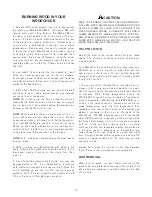
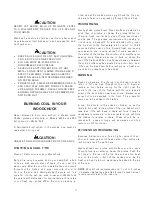
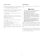
Never leave ash pan in unit. Use only when cleaning

out ashes. Ash pan will block the forced draft from com-

ing in under the fire from the forced draft blower.
The first thing to check is that your main blower and

draft blower are in working order before lighting a fire.

To check the operation of the main blower, push the

manual override button on the fan/limit control for test-

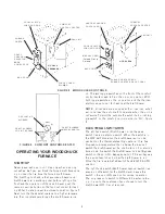
ing. When finished, reset to automatic position, figure 5.

Next, turn the thermostat upstairs to a higher tempera-

ture then room temperature so the draft blower turns

on. The two toggle switches on the front of the comfort

control center need to be in the up or on position. With

both toggle switches in the on position and the thermo-

stat turned up to call for heat, test the draft blower.
NOTE: All models are equipped with a “low limit” which

will not allow the auto draft to operate when the unit is

not warm. To start the auto draft, switch the Lo limit tog-

gle switch on the comfort control center to “On”, figure

6.

ELECTRICAL SWITCHES

The left hand switch (Draft blower lo-limit bypass

switch) is also a start up switch. When the switch is in

the OFF-AUTO position the draft blower will run de-

pendent on the thermostat setting upstairs. If fire has

dropped to a temperature that is below the low limit

switch the draft blower will be unable to run. For starting

from a cold fire switch the Draft Blower Lo-Limit Bypass

switch to the up or On-Bypass position. This will bypass

the low limit switch and allow the draft blower to run.

Once the fire is established switch back to OFF-AUTO

position.
The right hand switch (Draft blower manual switch) is a

simple on-off switch for the draft blower. Leave this

switch in the up or ON position for normal operation.

The only reason to switch to Off would be when refuel-

ing. It is up to the customer if you choose to turn the

draft blower Off. It is not required.

FIGURE 5 WOODCHUCK CONTROLS

COMFORT

CONTROL CENTER

DOUBLE LATCH

LOADING DOOR

SHAKER

GRATE

FORCED DRAFT

BLOWER

ASH DOOR

DRAFT

CHANNEL

SELECTOR -

80/20

COMBUSTION

MODELS

2900/4000

FAN/LIMIT

HEAT EXCHANGER

CONTROL ROD

COMFORT

CONTROL CENTER

DOUBLE LATCH

LOADING DOOR

MANUAL DRAFT

(Forced Draft Is

Optional)

ASH DOOR

SHAKER GRATE CRANK.

SHAKER GRATES ARE OPTIONAL

MODEL 526

FAN/LIMIT

FIGURE 6 COMFORT CONTROL CENTER

CIRCULATING

BLOWER

DRAFT BLOWER

LO-LIMIT BYPASS

DRAFT BLOWER

MANUAL SWITCH

Summary of Contents for WOODCHUCK 2900

Page 1: ...08 2012 Installation must be made in accordance with local and state codes which may differ from manual Save these instructions M a n u f a c t u r e d b y Meyer Mfg Corp Phone 715 654 5132 Fax 715 6...

Page 2: ...a Woodchuck Pride in craftsmanship and engi neering have made your Woodchuck the finest heating appliance available to day Solid fuels are abundant and inexpensive Wood is our only renewable source of...

Page 3: ...e 13 Trouble Shooting 14 General Requirements 16 Placement and Minimum Clearances 16 Installation 16 Chimney Installation 18 Installing Your Woodchuck 19 Stove Pipe Installation 19 Installation of a B...

Page 4: ...Door Rapidly Can Cause A Flame To Flash Out The Door Use Caution When Opening Loading Door Unsafe To Load Coal Above Top Of Brick Keep Ash Pan Out Of Unit During Operation Ash Pan Can Get Very Hot As...

Page 5: ...Secondary Heat Exchange YES Listings UL391 CSA B366 1 M ETLM Firebox Chamber 6 10 cu ft MODEL526 SPECIFICATIONS Height 48 5 Width 26 Depth 28 Blower 850 to 1850 CFM Max BTU Capacity 150 000 Log Size 2...

Page 6: ...on air must be warm when it enters the firebox to further pro mote complete combustion Your Woodchuck furnace provides all these features and more Here is how when combustion air enters a Woodchuck fu...

Page 7: ...ng for continuous air movement even during periods of low heat output this stratification is not allowed to take place You are more comfortable and lose less heat through your ceil ings as illustrated...

Page 8: ...WITHIN MARKED INSTALLATION CLEAR ANCES INSPECT AND CLEAN FLUES AND CHIMNEY REGU LARLY UNDER CERTAIN CONDITIONS OF USE CREO SOTE BUILDUP MAY OCCUR RAPIDLY WAIT 10 SEC ON FIRST LATCH BEFORE RE FUELING...

Page 9: ...pass switch is also a start up switch When the switch is in the OFF AUTO position the draft blower will run de pendent on the thermostat setting upstairs If fire has dropped to a temperature that is b...

Page 10: ...ostat up to activate auto draft and proceed as with manual draft Once the unit is warmed up you can turn the low limit by pass switch to OFF This will allow the auto draft to shut off if the unit runs...

Page 11: ...nds to give off large quantities of volatile gas This gas may accumulate and possibly ig nite causing a backpuff To reduce back puffing open the fire door to the first safety latch position for 15 20...

Page 12: ...pit will not allow the required air for combustion Keep ash pit clean ASH REMOVAL Ash should always be put into an air tight metal con tainer CAUTION KEEP ASH PAN OUT OF UNIT DURING OPERA TION ASH PA...

Page 13: ...onth to keep it tuned up and limber OPTIONAL CATALYTIC COMBUSTOR FOR MODELS 2900 4000 NOTE Optional catalyst not recommended for Model 2900 4000 with 6 flue adapter Smoke spillage may oc cur out of do...

Page 14: ...n Switch blower to the off position Bad wall Ther mostat check by turning it up to 80 and if the draft blower does not turn on replace thermo stat Lo limit bypass on off Replace thermostat When starti...

Page 15: ...r how good the conditions The use of wet frozen or unseasoned wood The use of soft wood particularly those of high resin content such as plywood or blandex with glue Poor natural draft or an obstructi...

Page 16: ...or oil fired fur nace or as a central furnace ELECTRICAL SUPPLY 115 volts 60HZ 1 Phase less than 12 amps Install system with 0 2 static pressure Flue setting 06 W C Max to 04 W C Min Wood or coal rela...

Page 17: ...FROOFWITHIN10 HORIZONTALLY ALSOSEEFIGURE9 ACHIMNEYWHICHRISESWITHINHOUSEISBETTER INSULATEDTHANACHIMNEYWHICHISLOCATEDOUTSIDE THEHOUSEANDISEXPOSEDTOWEATHER THECHIMNEYFLUEMUSTHAVEACROSSSECTIONALAREA ATLEA...

Page 18: ...y MAKE SURE YOUR WOODCHUCK IS IN STALLED INTO A PROPER CHIMNEY For maximum safety and efficiency never install the Woodchuck furnace into the same chimney serving an other appliance A typical chimney...

Page 19: ...t experts as to whether use of barometric draft regulators is wise Draft regulators limit the draft the suction pulling air into the appliance A pivoted counter balanced flap is pulled open by the dra...

Page 20: ...he plenum top may be dangerous so make sure clearances are maintained For the Model 4000 allow at least 4 from ceiling to plenum The ducts fittings grilles and registers should be sized so that the to...

Page 21: ...R GRATE INSTALLATION FOR MODEL 526 1 Remove standard grates from firebox Assemble com plete shaker grate kit outside of unit Figure 16 2 Assemble the left front bar different from right front bar has...

Page 22: ...bled grate on the loading door lower frame The grate should be the upside down position Slide the grate front end first into the firebox allowing the front end to lower into the hearth area Once the b...

Page 23: ...ks that will fit between the bevel cut bricks 4000 Models with have just two 2 thick bricks with bevel cuts that will fit to the outer walls of the firebox 3 Place rectangular brick along side walls o...

Page 24: ...to form a 90 angle This angle points toward the rear of the firebox FIGURE18 INSTALLOPTIONALCATALYTIC COMBUSTOR MODEL2900 4000 SLOTS IN EXHAUST PIPE CATALYTIC ELEMENT RODS ON RETAINER ASSEMBLE MANUAL...

Page 25: ...he rear of the fur nace Slide in from the top side figure 21 INSTALL FILTER BOX The filter box is standard on Model 526 Installation in structions are included with Model 526 filter box 1 The filter b...

Page 26: ...rt control These connections have been routed to a terminal strip on the outside of the comfort control box for convenient connection 4 The circulating blower limit control is factory wired to the com...

Page 27: ...SHOCK OR BURN DISCONNECT AND LOCKOUT POWER SOURCE BEFORE SERVICING OR INSTALLING ELECTRICAL COMPONENTS FAILURE TO HEED MAY RESULT IN SERIOUS PERSONAL INJURY OR DEATH CAUTION ALL WIRING MUST MEET LOCAL...

Page 28: ...r Pin 13 05 0004 Handle Access Cover 14 801 2520 1 5Z 1 4x1 1 2 Bolt KEY NO PART NO DESCRIPTION 15 06 0215 Spring 16 814 2520 Z 1 4 Lock Nut 17 05 0002 Small Grate 18 05 0001 Large Grate 19 07 5267 Fr...

Page 29: ...2902 Ash Door 12 06 1014 Handle Knob Large 13 02 2901 Fuel Door KEY NO PART NO DESCRIPTION 14 06 2902 Fuel Door Gasket 15 07 2901 Side Brick Kit 4 pc 16 07 2902 Rear Brick Kit 2 pc 17 07 2904 Front B...

Page 30: ...1014 Handle Knob Large 10 06 1013 80 20 Selector Knob 11 06 1001 Ash Pan 12 06 0200 Door Pin KEY NO PART NO DESCRIPTION 13 02 2901 Fuel Door 14 06 2902 Fuel Door Gasket 15 02 2902 Ash Door 16 06 2903...

Page 31: ...2903 End Rail W 10 3 05 2904 Shaker Bar CC 130 4 05 2905 Shaker Rail WC 2900 05 4001 Shaker Rail WC 4000 5 05 2906 Sleeve WC 2900 05 4003 Sleeve WC 4000 6 05 2908 Handle WC 2900 E423 05 2907 Handle W...

Page 32: ...Bracket 9 08 0112 Kit Motor Clamp 2 COVER not shown 08 0100 COMFORT CONTROL Item 8 10 11 12 Not Included Order Separately DRAFT Wiring Decal See Next Page 9 KEY NO PART NO DESCRIPTION 1 08 0100 2 Box...

Page 33: ...33 46 2900 8 Forced Draft Wiring Diagram...

Page 34: ...Purchase Date Of Installation Name Of Installer Address Phone HOW TO READ YOUR SERIAL NUMBER Your serial number is located on your Certification Panel Example 0085 3582 Model Code Sequence of Build 0...

Page 35: ...g or negligence or from an attempt to repair the unit by any person not expressly authorized by Meyer Manufacturing Corporation to do the repair Limit of Obligation No one is authorized to make any ot...

Page 36: ...Box 405 Dorchester Wisconsin 54425 ManufacturedBy MEYERMANUFACTURINGCORPORATION CountyHwy A West P O Box 405 Dorchester Wisconsin54425 0405 Phone 715 654 5132 FAX 715 654 5513 1 800 325 9103 www meye...

Reviews: