background image

51

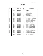
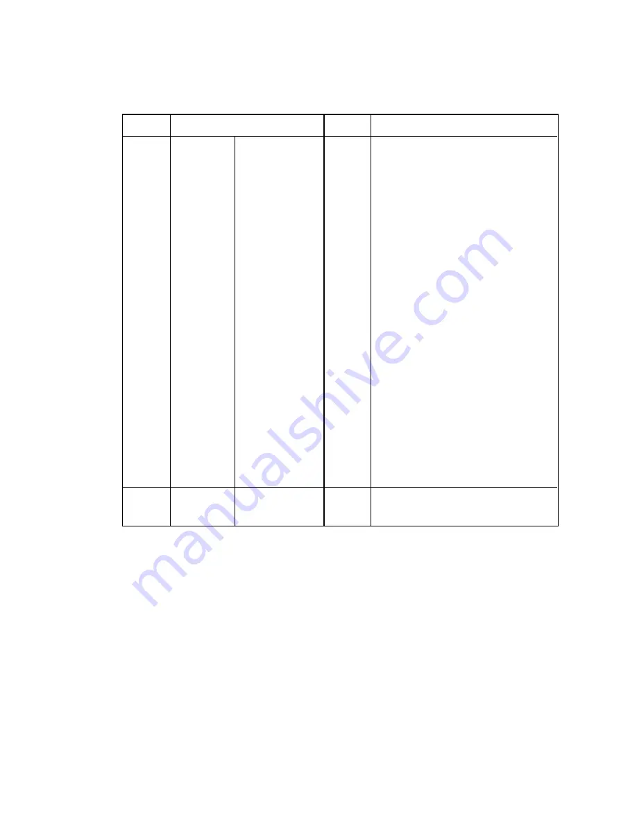
PARTS LIST FOR CONTROL PANEL ASSEMBLY

(62334)

ITEM

PART. NO.

QTY.

DESCRIPTION

1

62150

04622-038-00

1

Enclosure

2

62151

04640-026-00

2

Panel, End

3

62152

04640-027-00

1

Panel, Middle

4

62153

00114-161-00

1

Switch, START/CONV

5

62154

00114-162-00

1

Switch, Choke HI/LO

6

62155

00114-163-00

1

Switch, ON/OFF

7

62156

04638-039-16

3

Conn., double M/FM

10

62158

04622-039-00

1

Enclosure, Back Panel

11

62159

04002-059-04

4

Screw, #8 x 1/2 SM SLT HWH ZP

14

62161

00113-753-00

1

Jump Wire, 14 Ga., BLUE 3”

15

62162

00113-756-00

1

Jump Wire, 14 Ga., BROWN 5.5”

16

62163

00113-755-00

1

Jump Wire, 14 Ga., RED 4”

17

62164

00113-757-00

1

Jump Wire, 14 GA., BROWN 3”

18

62165

00113-754-00

1

Jump Wire, 14 Ga., RED 3”

21

62671

04638-102-00

1

Receptical, Sq. Flange

22

62672

04638-105-00

7

Connector, Socket, 14 Ga., Tin

23

62673

04616-016-00

.333

Wire, 14 Ga., White Insulated

24

62674

04616-037-00

.333

Wire, 14 Ga., Black Insulated

25

62675

04616-039-00

.333

Wire, 14 Ga., Red Insulated

26

62676

04616-022-00

.333

Wire, 14 Ga., Brown Insulated

27

62677

04616-040-00

.333

Wire, 14 Ga., Green Insulated

28

62678

04616-021-00

.333

Wire, 14 Ga., Blue Insulated

29

62679

04616-038-00

.333

Wire, 14 Ga., Yellow Insulated

30

62680

04638-045-06

7

Terminal Insulated Disc. Female

31

62177

04003-061-04

4

Screw, #4-40 x 1/2 Slt Rd HD

32

62178

04003-801-01

4

Nut, #4-40 Hex ZP

33

62179

04004-001-01

4

Lockwasher, #4 Med Split ZP

NOT SHOWN:

62519

00115-654-00

1

Cable, 7 Pin (Front Half)

PARTS LIST

Summary of Contents for Diamond 62209

Page 1: ...ENGINE 48 49 CONTROL BOX 50 51 OPTIONAL COMPONENTS 52 53 PARTS LIST SHIPPING CARTON 53 NAME PLATE INFORMATION 54 WARRANTY INFORMATION 55 WARRANTY REGISTRATION CARD 55 INDEX Diamond Equipment 6 Angell...

Page 2: ...ENANCE MANUAL FOR SPECIFIC SAFETY PRECAUTIONS FOR THIS ENGINE NOTICE Instructional Material And Parts Lists Included In This Manual Are Subject To Change Without Notice CAUTION 1 KEEP ALL SHEILDS IN P...

Page 3: ...lt the spinner to the longitudinals using the four 4 3 8 x 1 bolts 3 8 flange nuts and flatwashers from hardware bag located on the spinner Using one 1 3 8 x 1 bolt flatwashers and flange nut from har...

Page 4: ...ry from that shown Straps must be positioned at opposing angles so that spreader cannot slide forward or rearward Mount eye bolts as shown with locknuts and flatwashers on the bottom side Assemble rat...

Page 5: ...clutch black lead through the same hole which you put your throttle cable through 4 Wire up 2 conductor cable 16 to the control panel as Diagram A shows making sure the white conductor is connected t...

Page 6: ...6 DIAGRAM A BATTERY FRONT VIEW REAR VIEW BATTERY HOLD DOWN POST BLACK WHITE BLACK WHITE STARTER CHARGER WIRE 11 21 10 20 15 13 16 19 6 9 4 1 2 7 17 THROTTLE 3 14 5 12 18...

Page 7: ...4 Long 7 62049 04640 013 00 1 On Off Switch 8 62805 04638 040 06 1 Insulated Spade Terminal 9 92805 04638 040 06 2 Insulated Spade Terminal 10 62040 04604 004 00 2 19 Battery Cable 11 62046 04638 039...

Page 8: ...er for acceptable mounting locations Improperly mounting the control box could interfere with air bag s and the other functions of the occupant protection systems such as knee bolsters 5 After the loc...

Page 9: ...tery cable to the negative terminal of the battery 11 Connect the negative battery terminal to the battery hold down post When finished make sure all wires are away from moving parts and lower engine...

Page 10: ...g holes any bare metal should be coated with a rust preventative use appropriate size grommets and seal hole with appropriate sealant 3 Allow for normal movement twisting between cab and chassis picku...

Page 11: ...unt Stop Light 1 62714 04605 153 00 1 Lamp Stop 2 62715 04605 154 00 1 Grommet 3 62364 04605 155 00 1 Cable Light Power 4 62738 04616 075 00 1 Cable Stop Lamp 5 62283 00111 339 00 1 Weld Stop Lamp Bra...

Page 12: ...acturer s recommendations for fitting re useable hose ends 8 Hydraulic pumps must be mounted so shaft rotates in direction of arrow 9 Locate reservoir as close to pump as possible It may be installed...

Page 13: ...ealized between the flow valve and valve stand after the flow valve has been completely plumbed If this condition does not exist after the plumbing has been completed removal of valve will require hos...

Page 14: ...ontrol When the switch is in the OFF position the electric clutch is disengaged and the conveyor and spinner will stop In the ON position conveyor and spinner will operate The middle control is the th...

Page 15: ...TO ENGAGE Spreader Conveyor 1 Push CONVEYOR switch only after you are sure no one is in the hopper or near the spinner This lights up the red indicator light if light does not light take care to verif...

Page 16: ...he spreader the first time start and stop the conveyor several times to break in the clutch ALWAYS STAND AT A SAFE DISTANCE AWAY FROM THE SPINNER WHILE OPERATING ALWAYS WEAR EYE PROTECTION WHEN OUTSID...

Page 17: ...heir manuals DO NOT TRANSPORT ENGINE WITH FUEL IN TANK OR WITH FUEL SHUT OFF VALVE OPEN Failure in doing this may cause the engine crankcase to fill with fuel If this occurs the engine warranty will b...

Page 18: ...maintained It is adjusted by loosening the spinner mounting bearings and sliding the bearings Make sure the spinner shaft is straight up and down before retightening Oil chain often and at end of sea...

Page 19: ...Woodruff 9 62758 04101 035 09 1 Shaft Output 10 62809 04101 035 10 1 Housing 11 Seal O Ring 12 62759 04101 035 12 1 Drive For 04101 035 00 13 62760 04101 035 13 1 Plate Spacer 14 62761 04101 035 14 4...

Page 20: ...20 HYDRAULIC DRIVEN HOPPER SPREADER 25 18 19 26 27 28 29 11 5 28 29 43 56 2 28 29 43 41 40 44 23 1 3 43 4 6 7 8 10 12 13 13 54 16 18 19 31 19 20 21 17 16 54 42 12 35 21 34 34 used with gas engine 30...

Page 21: ...9 04624 001 01 1 Knob Hand 22 62281 00110 819 00 1 Weld Feedgate 23 60324 04101 035 00 1 Motor Hydraulic N S 62118 04101 102 02 1 Flange Mounting 4Bolt Char Lynn N S 62406 04101 102 09 1 Seal Kit Char...

Page 22: ...22 HYDRAULIC DRIVEN HOPPER SPREADER 25 18 19 26 27 28 29 11 5 28 29 43 56 2 28 29 43 41 40 44 23 1 3 43 4 6 7 8 10 12 13 13 54 16 18 19 31 19 20 21 17 16 54 42 12 35 21 34 34 used with gas engine 30...

Page 23: ...D 48 62640 04003 032 06 8 Bolt 5 16 18 x 3 4 Car GR5 SS 49 62314 00115 154 01 1 Guard Shaft 62364 04605 155 00 1 Cable Light Power 50 62283 00111 339 00 1 Weld Stop Lamp Bracket 62714 04605 153 00 1 L...

Page 24: ...24 HYDRAULIC DRIVEN HOPPER SPREADER 25 18 19 26 27 28 29 11 5 28 29 43 56 2 28 29 43 41 40 44 23 1 3 43 4 6 7 8 10 12 13 13 54 16 18 19 31 19 20 21 17 16 54 42 12 35 21 34 34 used with gas engine 30...

Page 25: ...04624 001 01 1 Knob Hand 22 62282 00110 819 01 1 Weld Feedgate S3 23 62398 04101 035 00 1 Motor Hydraulic N S 62118 04101 102 02 1 Flange Mounting 4Bolt Char Lynn N S 62406 04101 102 09 1 Seal Kit Ch...

Page 26: ...26 HYDRAULIC DRIVEN HOPPER SPREADER 25 18 19 26 27 28 29 11 5 28 29 43 56 2 28 29 43 41 40 44 23 1 3 43 4 6 7 8 10 12 13 13 54 16 18 19 31 19 20 21 17 16 54 42 12 35 21 34 34 used with gas engine 30...

Page 27: ...SS 48 62640 04003 032 06 8 Bolt 5 16 18 x 3 4 Car SS 49 62315 00115 154 02 1 Guard Shaft S3 62364 04605 155 00 1 Cable Light Power 50 62283 00111 339 00 1 Weld Stop Lamp Bracket 62714 04605 153 00 1 L...

Page 28: ...57 61 42 1 60 62 75 17 15 16 67 5 8 9 7 10 11 2 3 4 7 19 19 12 20 65 17 17 64 43 44 59 55 50 D A N G E R 18 74 51 52 63 60 47 M o to r 6 73 12 13 14 68 69 46 54 56 66 45 24 77 76 71 21 31 30 28 27 26...

Page 29: ...01 1 Floor Forming 7 Ft 1 8 62292 00115 109 01 1 Floor Forming 8 Ft 2 0 62555 00115 655 00 1 Assy Control Cable Briggs Stratton E T Pg 33 62701 00115 717 00 1 Assy Control Cable Honda Electric Throttl...

Page 30: ...57 61 42 1 60 62 75 17 15 16 67 5 8 9 7 10 11 2 3 4 7 19 19 12 20 65 17 17 64 43 44 59 55 50 D A N G E R 18 74 51 52 63 60 47 M o to r 6 73 12 13 14 68 69 46 54 56 66 45 24 77 76 71 21 31 30 28 27 26...

Page 31: ...3 04120 078 01 1 Hose 3 8 x 13 1 Wire Briggs Stratton 62706 04120 108 01 1 Hose Drain Honda N S 62632 04110 006 03 1 Elbow 3 8 90 Deg Street Briggs Stratton 62707 04121 057 01 1 Bolt Banjo Honda 62 62...

Page 32: ...57 61 42 1 60 62 75 17 15 16 67 5 8 9 7 10 11 2 3 4 7 19 19 12 20 65 17 17 64 43 44 59 55 50 D A N G E R 18 74 51 52 63 60 47 M o to r 6 73 12 13 14 68 69 46 54 56 66 45 24 77 76 71 21 31 30 28 27 26...

Page 33: ...Rep Chain 7 Ft S3 62311 00115 139 02 2 Shield Rep Chain 8 Ft S3 21 61162 04071 016 00 1 V Belt 22 62319 00115 172 02 1 Floor Forming 7 Ft S3 1 8 62293 00115 109 02 1 Floor Forming 8 Ft S3 2 0 62555 00...

Page 34: ...57 61 42 1 60 62 75 17 15 16 67 5 8 9 7 10 11 2 3 4 7 19 19 12 20 65 17 17 64 43 44 59 55 50 D A N G E R 18 74 51 52 63 60 47 M o to r 6 73 12 13 14 68 69 46 54 56 66 45 24 77 76 71 21 31 30 28 27 26...

Page 35: ...S 62633 04120 078 01 1 Hose 3 8 x 13 1 Wire Briggs Stratton 62706 04120 108 01 1 Hose Drain Honda N S 62632 04110 006 03 1 Elbow 3 8 90 Deg Street Briggs Stratton 62607 04121 057 01 1 Bolt Banjo Hond...

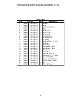
Page 36: ...36 DURST GEAR BOX ASSEMBLY 61178 7 5 7 5 3 8 4 15 20 16 23 9 18 22 10 11 19 2 1 17 14...

Page 37: ...1 4 Capscrew 3 8 x 3 4 H H 12 62037 04132 074 12 1 Shaft Input 13 62032 04132 065 13 1 Shaft Output 14 62029 04132 061 14 1 Woodruff Key Hard 15 62024 04009 002 01 1 Woodruff Key Hard 16 61166 04132 0...

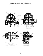
Page 38: ...20 B 17 18 CW CW 22 21 B 25 15 8 1 13 5 7 10 23 19 Section A A 3 2 A A 12 4 24 11 9 16 7 6 Section B B Notes 1 Gear Ratio is 20 1 2 Torque 3 8 16 Capscrews 20 21 to 35 40 ft lbs SUPERIOR GEARBOX ASSE...

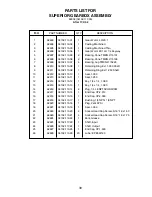
Page 39: ...haft 10 62912 04132 113 10 1 Seal 1 000 11 62913 04132 113 11 1 Seal 1 250 12 62914 04132 113 12 1 Key 1 4 x 1 4 1 080 13 62915 04132 113 13 1 Key 1 4 x 1 4 1 580 14 62916 04132 113 14 4 Plug 1 4 18 N...

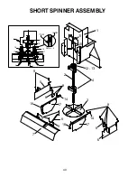
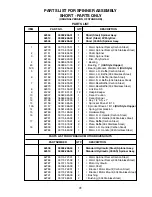
Page 40: ...40 DANGER CAUTION 1 12 13 4 2 9 14 3 9 9 8 8 7 17 9 5 18 16 17 8 6 14 9 SHORT SPINNER ASSEMBLY 11 10 17 18 5 3 6 17 16 17 REF 18 REF CAUTION DANGER DETAIL A 1 11 10...

Page 41: ...anger 12 61196 04031 007 00 1 Key 1 4 Sq x 1 13 61156 04041 085 00 1 Sprocket Drive 41 B 13 13b 61157 04041 086 00 1 Sprocket Drive 41 B 19 Old Style Hopper 14 62358 04091 028 00 2 Spring Compression...

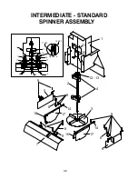
Page 42: ...42 DANGER CAUTIO N 1 12 13 4 2 9 14 3 9 9 8 8 7 17 9 5 18 16 17 8 6 14 9 INTERMEDIATE STANDARD SPINNER ASSEMBLY 11 10 17 18 5 3 6 17 16 17 REF 18 REF CAUTION DANGER DETAIL A 1 11 10...

Page 43: ...62007 04049 045 00 1 Decal Caution 11 62006 04049 044 00 1 Decal Danger 12 61196 04031 007 00 1 Key 1 4 Sq x 1 13 61156 04041 085 00 1 Sprocket Drive 41 B 13 13b 61157 04041 086 00 1 Sprocket Drive 4...

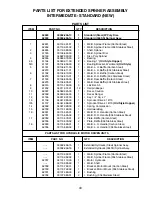
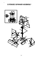
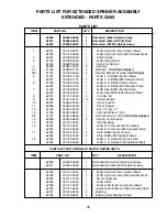
Page 44: ...44 EXTENDED SPINNER ASSEMBLY DANGER CAUTION 1 12 13 4 2 9 14 3 9 9 8 8 7 17 9 5 18 16 17 8 6 14 9 11 10 17 DANGER CAUTION 11 10 1 18 17 DETAILS A 16 5 3 6 DETAIL A 16 REF 17 REF...

Page 45: ...eper 10 62007 04049 045 00 1 Decal Caution 11 62006 04049 044 00 1 Decal Danger 12 61196 04031 007 00 1 Key 1 4 Sq x 1 13 61156 04041 085 00 1 Sprocket Drive 41 B 13 13b 61157 04041 086 00 1 Sprocket...

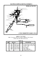
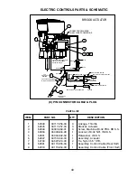
Page 46: ...or That is red to red black to black etc PARTS LIST 7 PIN CONNECTOR CABLE PLUG HONDA ACTUATOR POSITIVE FROM BATTERY TO CENTER TAB ON SOLENOID TO CLUTCH POWER WIRE SOLENOID CONNECT TO KILL WIRE FROM EN...

Page 47: ...14 62339 04008 007 00 2 Bushing Spacer S S 15 62519 00115 654 00 1 Assembly Control Cable Front Half 16 62701 00115 717 00 1 Assembly includes items 1 thru 11 17 Rear Half PARTS LIST WIRE HARNESS SUP...

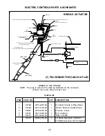
Page 48: ...ThrottleConversion Kit Complete 7 PIN CONNECTOR CABLE PLUG POSITIVE FROM BATTERY FROM STARTER TO CENTER STUD ON SOLENOID TO CLUTCH POWER WIRE SOLENOID CONNECT TO KILL SWITCH TAB INSTALL KILL CONNECTI...

Page 49: ...RIGGS ACTUATOR 9 8 Pin ConductorCable Front Half 8 Pin ConductorCable Rear Half ITEM PART NO QTY DESCRIPTION 1 62648 00117 256 00 3 Linkage Throttle 2 62645 00117 257 00 3 Bracket Actuator 3 62649 040...

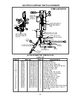
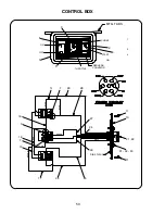
Page 50: ...GREEN GREEN GREEN BLACK BLACK BLACK BLACK WHITE WHITE WHITE WHITE WHITE WHITE WHITE BROWN BROWN BROWN BROWN BROWN BROWN BROWN BROWN BROWN BROWN BROWN BROWN BROWN BROWN BROWN BLUE BLUE BLUE YELLOW YELL...

Page 51: ...1 Jump Wire 14 GA BROWN 3 18 62165 00113 754 00 1 Jump Wire 14 Ga RED 3 21 62671 04638 102 00 1 Receptical Sq Flange 22 62672 04638 105 00 7 Connector Socket 14 Ga Tin 23 62673 04616 016 00 333 Wire...

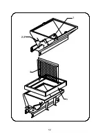
Page 52: ...52 2 3 1 22...

Page 53: ...inless Steel 7 Ft Unit Kit 62194 00002 177 04 1 6 Extension Carbon Steel 8 Ft Unit Kit 62145 00002 177 05 1 6 Extension Stainless Steel 8 Ft Unit Kit ITEM PART NO QTY DESCRIPTION 1 62547 04046 016 06...

Page 54: ...s provided as a convenient place to record these numbers just fill in the blanks Model No ___________________________________________________________ Serial No ________________________________________...

Page 55: ...FROM ANY CLAIMS ARISING HEREUNDER OR FOR DAMAGES RESULTING FROM LACK OF NECESSARY MAINTENANCE OR FROM MISUSE ACTS OF GOD ALTERATION OF A MEYER OR DIAMOND PLOW SPREADER OR PART OR FROM USE OF PARTS OR...

Page 56: ...56 Meyer Products 18513 Euclid Avenue Cleveland Ohio 44112 1084 Postage Required...

Reviews: