12
1 X 78 en
Lift the body cap on top of body and smoothly
attach body halves.
Tighten at least 2 body flange joint nut at opposite
sides.
Lift the valve under the clamp and compress body
flanges together (metal to metal contact).
Operate the valve and if the torque is reasonable
(operable with hand lever), tighten all body flange
nuts.
Measure the torque and compare it to values in
Table 4.
If the measured torque meets the value given in the
table, finish the assembly (see below).
If the measured torque exceeds these limits, disman-
tle body flange joint and lift body cap on the table
(do not drop seat).
Remove from body cap back seal stack one 0.4 mm
thick shim. Repeat the assembly as described earlier. If
the torque is still too high remove one 0.4 mm shim
from body back seal stack. Continue until appropriate
torque is achieved.
Accordingly, if the torque is too low, add one 0.4 mm
shim.
Finish the assembly, see below.
Do not forget to change the V-ring set, if used, back
to graphite rings.
Tightness requirement meets ISO 5208 Rate D. Test pressure
is 6 bar with air. If the valve leak exceeds the allowable lim-
its, relap seats, check the torque and measure tightness
again.
(
NOTE:
Torque values on Table 4 do not include torque
caused by graphite packing).
All versions:
Place the shaft partly inside the body from above and
place the thrust bearings (70, 71) on the shaft from
inside the body. Place the spline driver (part 4, sizes
2"-8") on the shaft spline and lock it with a pin (50).
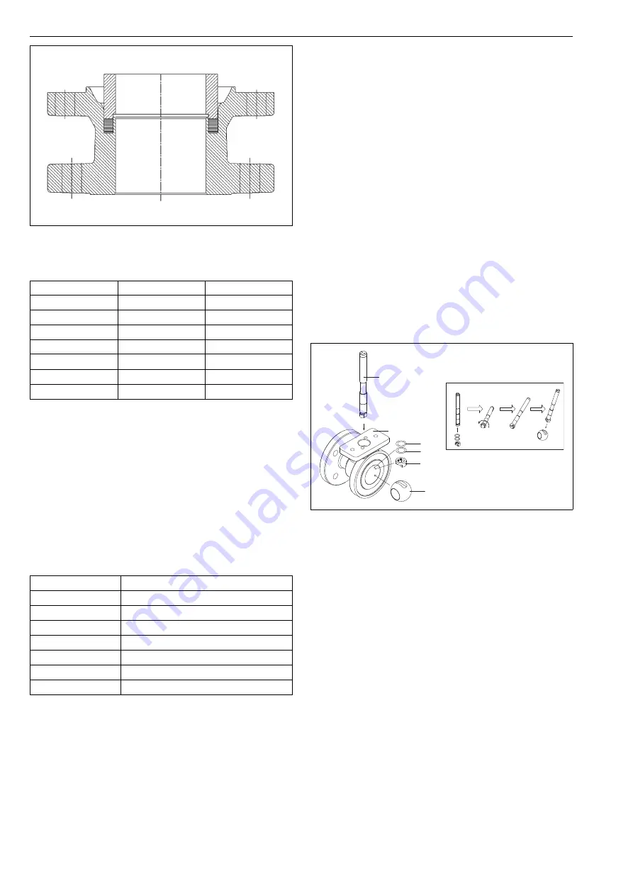
Place the thrust ring (4, sizes 1"-1 1/2") on the shaft
and lock it as illustrated in Fig. 31. Put the ball (3) in its
position so that the spline driver is in the ball slot. Pull
the shaft to make sure that the pin locks the spline
driver properly to the shaft. Place the packing (69), the
removed stud (14) and the gland (9) in their position.
Place the nuts (18) on the studs (14) and screw down
them gently.
Place the body gasket (65) in the body groove.
S seats:
Place the seat on the ball.
Soft seats (X, T):
Place the seat on the ball.
All versions:
Carefully place the body cap (2) on the body. Make
sure that the marks made during dismantling are
aligned.
Do not drop the H seat from the body
cap!
Fasten the body nuts (16). Tighten the nuts gradually,
always switching to other side of the valve after every
nut. In sizes 1” and 1 1/2” there are through holes both
in body and cap and the joint is made with nuts in both
ends of the studs. The recommended torques are given
in Table 5. The flange faces must be in even contact
with each other.
Mount the key (10).
To make sure that the ball lies properly between the
seats, turn the shaft slowly in both directions two or
three times.
Deform the packing rings by tightening the gland
nuts without disc springs to the torque Tt, see the
value from Table 1, see Section 4.2.
Fig. 30
Compressing the J seat
Table 3
Compression force
Valve size
Tool ID
Force (kN / lbf)
1''
H087299
8 / 1800
1H''
H087298
17 / 3822
2''
H087297
20 / 4497
3'' H097570
35
/
7869
4'' H087295
50
/
11241
6'' H087296
70
/
15738
8'' H135972
100
/
22481
Table 4
Testing torques
Valve size
Torque (Nm / lbf•ft)
1"
10 ± 2 / 8 ± 2
1H"
20 ± 4 / 15 ± 3
2"
30 ± 7 / 23 ± 6
3"
70 ± 14 / 52 ± 11
4"
150 ± 20 / 111 ± 15
6"
460 ± 60 / 340 ± 45
8"
925 ± 120 / 682 ± 89
Fig. 31
Assembling the shaft in sizes 1" and 1 1/2"
5
70
4
3
1
70/71
Summary of Contents for XB/XC Series
Page 23: ...1 X 78 en 23 ...


