background image

4

1 X 78 en

Identification plates have the following markings:

1.

Body material

2.

Shaft material

3.

Trim material

4.

Seat material

5.

Maximum and minimum operating temperatures

6.

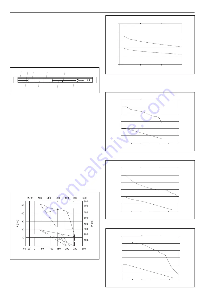
Maximum shut-off pressure differential/temperature

7.

Pressure class

8.

Type code

9.

Number of the list of valve manufacturing parts

10.

Model  

1.4

Technical specifications

Face-to-face length:
XT/XA:

ASME B.16.10

XB/XC:

ASME B.16.10 short pattern

Body rating:

ASME Class 150, 300

Max pressure differential:

see Figs. 6 and 7

Temperature range:

see Figs. 8, 9 and 10

Flow direction:
seats S, K, X and T:

free

Seats H and G:

see Figs. 1, 2 and 3
The arrow indicates the
recommended flow direction

Leakage rates:
metal seated

ISO 5208, leakage rate C

soft seated

ISO 5208, leakage rate A

Dimensions:

see Section 11

Weight:

see Section 11          

Fig. 5

Identification plate

Fig. 6

Valve seat rating, soft seats

BODY

TRIM

SHAFT

SEAT

T max

T min

MAX. OPER.        ps

at

RATING

TYPE

No.

MOD

ATTENTION : READ INSTRUCTIONS BEFORE INSTALLATION OR SERVICING. CONTACT METSO FIELD SYSTEMS FOR COPY.

MADE BY METSO AUTOMATION

XXXX

(1) (2)

(5)

(7)

(8)

(3) (4)

(6)

(9)

(10)

1" – 4" / DN 25 – 100, full bore
3" – 6" / DN 80 – 150, reduced bore

6" / DN 150, full bor

e

8" / DN 200, reduced bor

e

8" / DN 200, full bore

T*

T*

T*

T (°F)

T (°C)

T* = available only on request

Fig. 7

Maximum operational pressure differential, metal-
seated ASME Class 300 valves. Smaller sizes and ASME
Class 150 valves are full rated.

Fig. 8

Body pressure/temperature rating, WCB

Fig. 9

Body pressure/temperature rating, CF8M

Fig. 10

Body pressure/temperature rating, C5

50

750

600

450

300

150

0

40

30

20

10

0

100

T (°C)


P (psi)

°F)

(


T

P

 (bar)

0

300

200

6" full bore
8" reduced bore

8" full bore

400

500

600

750

400

NOTE! All sizes withstand full design shut off pressure 
(50 bar/750 psi) at ambient temperature

ASME 150

ASME 300

60

p (bar)

p (psi)

50

40

30

20

10

0

100

T (°C)

T (°F)

0

300

200

400

500

600

0

150

300

450

600

900

750

400

750

60

p (bar)

p (psi)

50

40

30

20

10

0

100

T (°C)

T (°F)

0

300

200

400

500

600

0

150

300

450

600

900

750

400

750

ASME 150

ASME 300

60

p (bar)

p (psi)

50

40

30

20

10

0

100

T (°C)

T (°F)

0

300

200

400

500

600

0

150

300

450

600

900

750

400

750

ASME 150

ASME 300

Summary of Contents for XB/XC Series

Page 1: ...1 X 78 en 1 2016 SEAT SUPPORTED BALL VALVES Series XT XA and XB XC Installation Maintenance and Operating Instructions ...

Page 2: ...Actuator 7 3 4 Commissioning 7 4 MAINTENANCE 7 4 1 Maintenance general 7 4 2 Replacing the packing without removing the valve from the pipeline 7 4 3 Repairing a jammed or stiff valve without removing it from the pipeline 8 4 4 Detaching the B series actuator 8 4 5 Removing the valve from the pipeline 9 4 6 Dismantling the valve 9 4 7 Checking the parts of a dismantled valve 10 4 8 Replacing parts...

Page 3: ...of the valves may vary in accordance with customers wishes The construction details are indicated in the type code in the identification plate For more informa tion about the type code see Section 12 1 3 Valve markings Body markings are cast or stamped on the body see Fig 4 The identification plate Fig 5 is on the valve flange NOTE As the use of the valve is application specific a number of factor...

Page 4: ...INSTRUCTIONS BEFORE INSTALLATION OR SERVICING CONTACT METSO FIELD SYSTEMS FOR COPY MADE BY METSO AUTOMATION XXXX 1 2 5 7 8 3 4 6 9 10 1 4 DN 25 100 full bore 3 6 DN 80 150 reduced bore 6 DN 150 full bore 8 DN 200 reduced bore 8 DN 200 full bore T T T T F T C T available only on request Fig 7 Maximum operational pressure differential metal seated ASME Class 300 valves Smaller sizes and ASME Class15...

Page 5: ... type of medium involved Protect people and the environment from any harmful or poisonous sub stances Make sure that no medium can enter the pipeline during valve maintenance Failure to do this may result in damage or personal injury CAUTION Beware of the ball cutting movement Keep hands other parts of the body tools and other objects out of the open flow port Leave no foreign objects inside the p...

Page 6: ...the pipeline may then enter the body cavity and damage the gland packing The position to be avoided is shown in Fig 13 It may be necessary to firmly support the pipeline in order to protect the valve from excess stress Sufficient support will also reduce pipeline vibration and thus ensures proper functioning of the positioner To facilitate servicing it is preferable that the valve be sup ported by...

Page 7: ...our local Metso experts During this periodic inspection the parts detailed in the Spare Part Set should be replaced Time in storage should be included in the inspection interval Maintenance can be performed as presented below For maintenance assistance please contact your local Metso office The part numbers in the text refer to the exploded view and to the parts list in Section 10 unless otherwise...

Page 8: ...essurized and tighten the nuts 18 more if needed 4 3 Repairing a jammed or stiff valve without removing it from the pipeline Jamming or stiff function may be caused by a flow medium clogging the seat 7 25 and the ball 3 The ball and the seats can be cleaned without removing the valve from the pipeline by turning the ball to a partly open position and flushing the pipes If this does not help follow...

Page 9: ...dy cap keep it from falling while you are lifting it out by putting your fingers under the body cap small sizes or in the flow bore large sizes Watch out for your hand Lower the body cap onto the surface in a standing position i e onto its flange See Fig 19 Remove the seat 7 25 from the body cap making sure that it is not damaged during the operation If the seat is of a locked type use a special t...

Page 10: ...ling it outwards The thrust bearings 70 will be detached around the stem Remove the locked seat 7 using an outpulling tool see Fig 23 See also Section 8 Tools 4 7 Checking the parts of a dismantled valve Clean the removed parts Check the shaft 5 and the thrust bearings 70 Check the ball 3 and the ball seats 7 25 Check the body gasket surfaces Replace any damaged parts 4 8 Replacing parts Replace s...

Page 11: ...nstall back seals 63 as per Table 2 to both body halves The seal on top of stack shall always be 1 mm thick and the others are either 1 mm or 0 4 mm Set back seal pressing tool on top of seal stack as seen in Fig 30 Compress back seal stack with pressing tool using forces found on the Table 3 Avoid damaging sealing faces of the flange during compression Let the com pression of the back seal stack ...

Page 12: ...izes 1 1 1 2 on the shaft and lock it as illustrated in Fig 31 Put the ball 3 in its position so that the spline driver is in the ball slot Pull the shaft to make sure that the pin locks the spline driver properly to the shaft Place the packing 69 the removed stud 14 and the gland 9 in their position Place the nuts 18 on the studs 14 and screw down them gently Place the body gasket 65 in the body ...

Page 13: ... Place the back seal 75 back up ring 76 spring 62 and the seat 25 with back seal 64 into insert see Fig 28 All seat versions Place the shaft partly inside the body from above and place the thrust bearings 70 on the shaft from inside the body Place the spline driver 4 on the shaft spline and lock it with a pin 50 Put the ball 3 in its position so that the spline driver is in the ball slot Pull the ...

Page 14: ...ue the reassembly as described in the earlier sec tion 5 TESTING THE VALVE Test the valve s body pressure after reassembly Test the pressure in accordance with an applicable standard Use thepressurerequiredbythepressureclassortheflangebore Keep thevalveinthehalfopenpositionduringthetest If the tightness of the closure member is also to be tested please contact the manufacturer If testing according...

Page 15: ...rews located at both ends see Fig 35 An accurate open position can be seen in the body flow bore Check that the yellow arrow on the actuator indicates the ball flow opening position Keep fingers out of the flow bore There is no need for stop screw adjustment if the actuator is re installed in the same valve Drive actuator piston to the housing end open position Turn the actuator by hand until the ...

Page 16: ... of actua tors not installed by Metso Extractor tools Actuator Series B1C B1J Product ID B1C B1J 6 303821 B1C 8 11 B1J 8 10 8546 1 B1C 12 17 B1J 12 16 8546 2 B1C B1J 20 8546 3 B1C B1J 25 8546 4 B1C B1J 32 8546 5 B1C 40 B1J 322 8546 6 B1C 50 8546 7 B1C 502 8546 8 Seat removal tools Product ID DN 25 1 270073 DN 40 1 270075 DN 50 2 270076 DN 80 3 270078 DN 100 4 270079 Seat locking tools Insertion to...

Page 17: ...e part category 1 1 Body 2 1 Body cap Insert 3 6 DN 80 150 reduced bore 3 1 Ball Q TRIM ball 3 4 1 Spline driver 2 8 DN 50 200 Thrust ring 1 1 1 2 DN 25 DN 40 3 5 1 Shaft 3 7 2 1 Ball seat S K seat Ball seat H G seat 2 9 1 Gland 10 1 Key 3 12 4 12 Stud quantity depends on valve size not in reduced bore 3 6 DN 80 150 14 2 Stud 16 6 12 Hexagon nut quantity depends on valve size not in reduced bore 3...

Page 18: ...9 00 13 50 16 93 8 00 18 74 15 16 0 50 3 54 2 17 2 39 3 58 418 Type Size ISO flange Dimensions mm kg A A1 ØB ØB1 ØD E K M N ØO P R XA_D 1 F07 165 74 125 110 25 4 175 150 4 76 25 15 17 25 7 1 1 2 F07 190 70 155 145 38 1 202 168 4 76 35 20 22 34 11 2 F07 F10 216 89 0 165 146 50 8 215 168 6 35 46 25 27 8 47 15 3 F07 F10 F12 F14 282 141 0 210 195 76 2 237 190 6 35 46 25 27 8 47 35 4 F10 F12 14 305 152...

Page 19: ...12 0 0 50 3 15 1 77 1 98 3 19 353 Type Size ISO flange Dimensions mm kg A A1 ØB ØB1 ØD E K M N ØO P R XC 3 F07 F10 282 100 210 50 8 215 168 6 35 46 25 27 8 47 31 4 F07 F10 F12 F14 305 107 255 76 2 237 190 6 35 46 25 27 8 47 50 6 F10 F12 F14 403 126 320 101 6 309 250 9 52 58 35 39 1 59 110 8 F14 F16 419 209 5 380 353 152 4 386 305 12 70 80 45 50 4 81 235 Type Size ISO flange Dimensions in lb A A1 Ø...

Page 20: ...9 B1C20 34 65 23 23 15 16 3 82 8 46 1 2 161 B1C25 42 32 28 54 17 64 4 76 10 43 1 2 289 B1C32 53 94 36 22 20 67 6 02 15 55 3 4 564 B1C40 65 75 45 28 23 43 7 64 19 88 3 4 983 B1C50 81 10 54 72 27 17 9 53 24 02 1 1829 Type Dimensions mm NPT kg F G J V X B1J B1JA6 485 368 283 36 110 3 8 13 B1J B1JA8 560 420 279 43 135 3 8 17 B1J B1JA10 650 490 290 51 175 3 8 30 B1J B1JA12 800 620 316 65 215 1 2 57 B1J...

Page 21: ...180A 2 7 09 1 1 2 LX220A 2 32 8 66 2 3 LK350 2 05 13 78 3 4 LK350 2 05 13 78 3 4 LK450 2 05 17 72 4 6 LK450 2 05 17 72 K J L Actuator size Dimensions mm kg F G J V ØZ M07 235 184 65 52 160 3 8 M10 238 187 65 52 200 4 4 M12 307 238 88 71 315 10 1 M14 385 285 93 86 400 18 2 M15 456 346 102 105 500 26 2 M16 530 387 124 130 500 36 8 M25 597 412 160 182 600 60 8 Actuator size Dimensions in lb F G J V Ø...

Page 22: ...tal bearings cobalt based alloy Live loaded graphite packing Temperature range 50 200C TZ BAM tested non metallic parts for oxygen service Double seated Metal bearings Live loaded graphite packing Temperature range 50 200C Oxygen cleaning acc to Metso internal procedure T 2115 included 6 sign BODY MATERIAL J2 ASTM A216 gr WCB S6 ASTM A351 gr CF8M J5 ASTM A217 gr C5 7 sign BALL COATINGANDSTEMMATERI...

Page 23: ...1 X 78 en 23 ...

Page 24: ...01 Sorocaba São Paulo Brazil Tel 55 15 2102 9700 Fax 55 15 2102 9748 Asia Pacific Haw Par Centre 06 01 180 Clemenceau Avenue Singapore 239922 Tel 65 6511 1011 Fax 65 6250 0830 China 11 F China Youth Plaza No 19 North Rd of East 3rd Ring Rd Chaoyang District Beijing 100020 China Tel 86 10 6566 6600 Fax 86 10 6566 2583 Middle East Roundabout 8 Unit AB 07 P O Box 17175 Jebel Ali Freezone Dubai United...

Reviews: