


6
8 ACE 71 en
2.3.3
Error signal connections
Error signal is available at connector X3, pins 3 and 4.
The following errors are indicated:
no supply voltage to limit switches.
overheating of controller, >85 °C.
shot circuit in motor winding.
blow out of controller fuse.
2.3.4
Cable connections for actuator
Two cables are connected to the actuator. The first is con-
nected to the connector cover of actuator which has the
connections of the limit switch and the feedback potenti-
ometer, Fig. 6. The second cable is connected to the step
motor, Fig. 7. The cables are connected as shown in Fig. 3.
3
COMMISSIONING
Check the following proceedings at commissioning:
Check connections.
Check grounding.
Connect power supply.
Check that LED 11 is lit (HW Enable), see Fig. 5.
Move valve to open and close limits in manual mode.
Check functioning of limit switches and position display.
Connect control unit to automatic mode and check
that the valve is also operable with the signal from
control system.
Fig. 5
Connector card
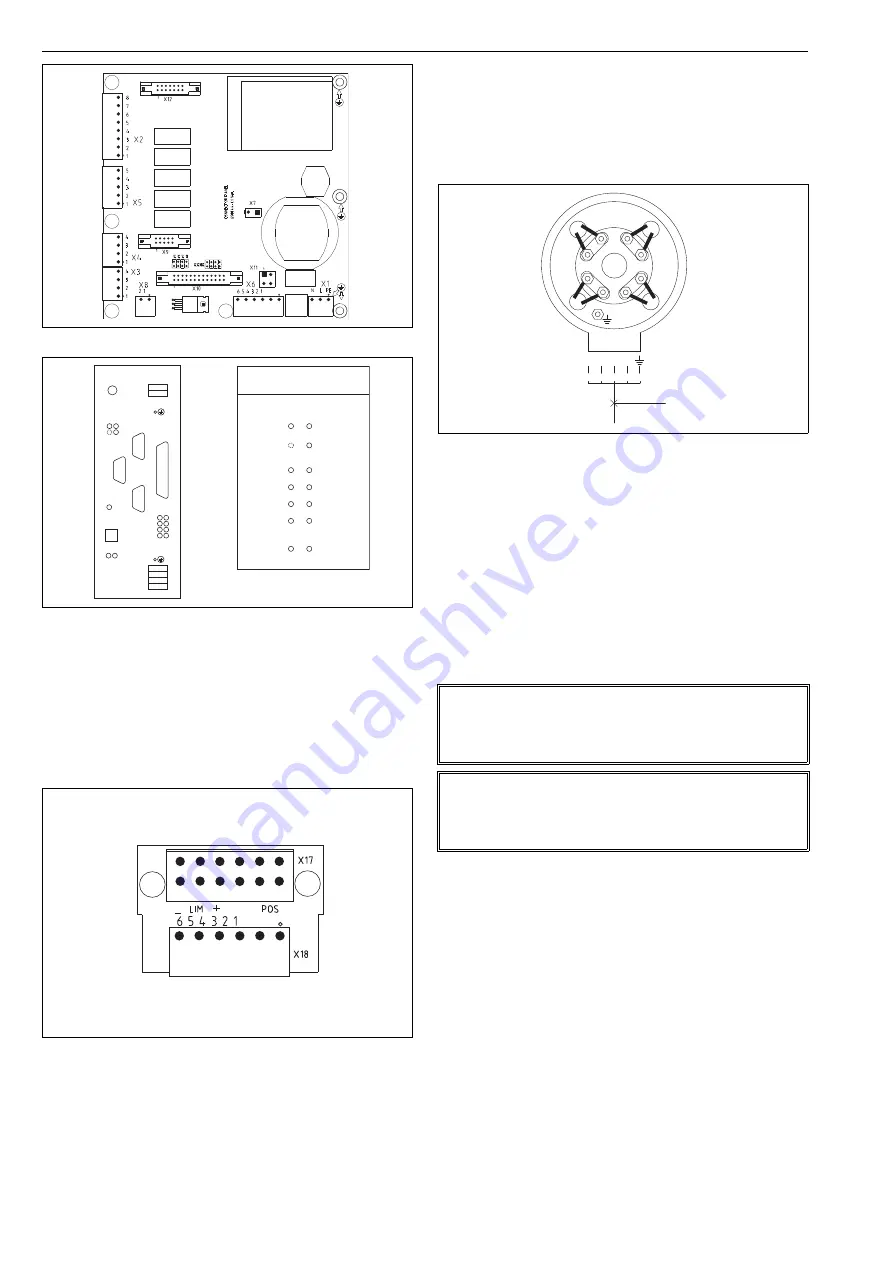
Fig. 6
Connectors and LEDs for step motor controller
Fig. 7
Connector cover
S1
LED
LED
X6
X2
X3
F1
X1
LED
X5
X4
T1
13
12
5
6
7
8
1
2
3
4
A
B
C
D
10
9
11
1
1
1
Fuse
Mains
L
N
1
– Limit switch
+ Limit switch
10
9
HW Enable
11
5
1
Outputs OK
Outputs OK
READY
6
2
ERROR
Reset GSP
7
3
SW Enable
8
4
Reset error
Strobe
12
13
STATUS
POWER
LEDs
14
14
Option
Fig. 8
Connection for step motor
NOTE:
When replacing the existing basis weight valve with
NelesAce it is recommended to you verify and, if neces-
sary, tune DCS parameters.
NOTE:
It is recommended that the valve position signal is used
only for informative purposes and feedback for control is
taken from other measures, e.g. flow.
2
4
6
8
1
2
3
4
5
5x1.5S
3
4 5
6
7
81
2


