8
4.5
Removing the valve from the pipeline
Make sure that the valve is not pressurized and that
the pipeline is empty. Make sure that the medium
cannot flow into the section where servicing is to
take place.
Support the valve carefully with a hoist. Place ropes
carefully and unscrew the pipe flange bolts. See that
the ropes are positioned correctly, see Fig. 6. Lift
valve down.
4.6
Dismantling the valve
Place the valve in a standing position on the pipe
flange end. Use a level surface that will not scratch the
flanges. See that the body stud nuts (16) are facing
upward.
Mark the the body halves for correct orientation during
re-assembly.
Turn the ball to the closed position.
Remove the key (10).
Unscrew the gland nuts (18). Remove the disc spring
sets (150), the gland (9A), retainer ring (42) and
sleeve (9B)..
Unscrew the body stud nuts (16).
Remove the body cap (2). If the seat (7) is not lying on
the ball (3), prevent the seat from falling from the body
cap and detach it later.
Don’t leave your fingers
between the body cap and the surface!
Stand the removed body cap on its pipe flange.
Remove the seat (7) from body cap (2) if it is still in
place.
Unscrew the bonnet stud nuts (17). Remove the
shaft (5) and bonnet (8). Knock the bonnet off with a
piece of wood and a hammer, if needed.
Lift the ball (3) along with the trunnion plates (89)
and bearings (91, 99) out of the body (1) Handle the
ball carefully and place it on a soft surface.
Remove the seat (7) from the body (1).
Remove the trunnion plates (89) from the hubs of the
ball.
Remove the trunnion bearings (99) and the thrust
bearing (91) from each trunnion.
Push the shaft out of the bonnet.
Remove thrust bearings (70) from the shaft and
packing rings (69) from the bonnet (8).
Remove the body gasket (65) and the bonnet gasket
(66).
4.7
Inspection of removed parts
Clean removed parts.
See if the shaft (5) or bearings (70, 99) are damaged.
See if the ball (3) or seats (7) are damaged (scratched),
by examining them under bright light. The ball and the
seat can be replaced if necessary.
See if the body joint sealing surfaces are damaged.
4.8
Replacing parts
We recommend that soft material parts be replaced when-
ever the valve is dismantled for servicing. Other parts may
be replaced if necessary. Always use genuine spare parts to
ensure proper functioning of the valve (see section “Order-
ing spare parts”).
4.9
Assembly
Place the valve body (1) and the body cap (2) on the
pipe flange end. Use a level surface that will not scratch
the flanges.
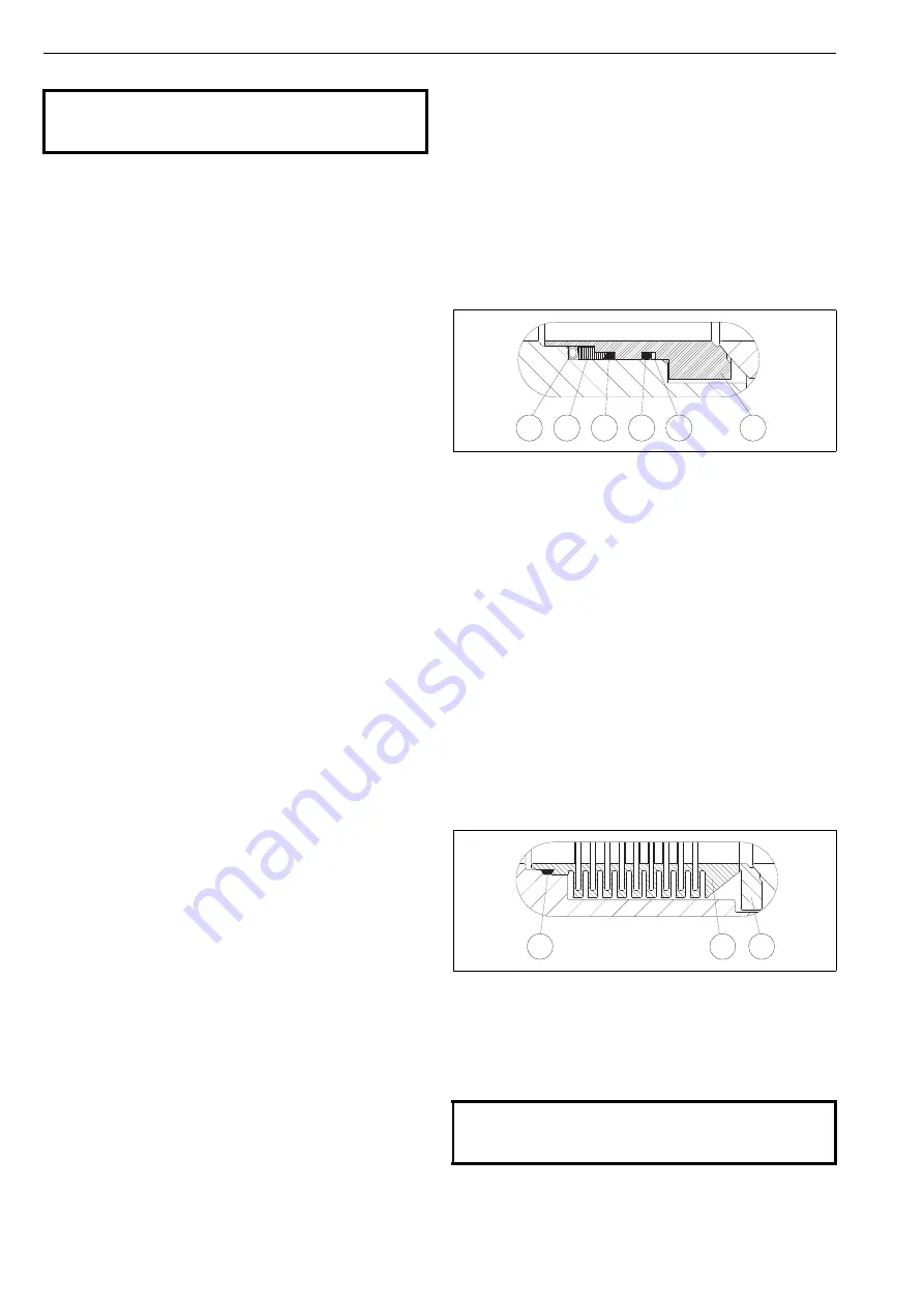
R seat:
Check the sealing surfaces.
Place the back seal (O-ring) (63) into the groove in the
seat. See Figure 12.
Place the back-up rings (64) made of PTFE strips at the
side of the O-ring. To ensure that the seam becomes
flexible, the strip must have slanted ends.
For easier assembly, lubricate the O-ring and back-up
ring surfaces facing the seats with silicone grease or
another suitable substance. Please ensure the compati-
bility with the flow medium. Place the backseal (130)
and ring (129) on the seat.
Place the spring (62) on the seat (7). Connect the
ends of the spring.
Place the seats into the body and body cap by hand
or if necessary, using a plastic mallet. The seat is in
correct position when the spring touches the body
shoulder.
F seats:
Check the sealing surfaces.
Place the back seal (63) into the bellows (62). See Fig-
ure 13.
Place the bellows and seat (7) into the body counter-
bore.
CAUTION:
Do not dismantle the valve or remove pipeline while the
valve is pressurized!
Fig. 12
S seat
Fig. 13
F seat
CAUTION:
Be careful not to damage the lapped surfaces of the bel-
lows and the seat.
129 130
7
63
64
62
63
62
7
Summary of Contents for NELES XH Series
Page 15: ...15 ...


