4 KH 70 en
5
The incorrect position or installation of the flanges
can cause deformations on the valve’s body and this
could lead to operating problems.
It is very important to make sure that the valve is cor-
rectly aligned and parallel to the flanges to prevent
leakages and avoid deformations. Ensure the valve is
assembled in open position.
The screws in the tapped blind holes will have a
maximum depth (Fig. 2) and will never reach the
bottom of the hole. The following table (Table 1)
shows the maximum thread depth in the holes and
the maximum torque to be applied to the flange
screws:
Fig. 2
Tabla 1
The equipment must be firmly installed in the pipe.
It will be joined to the pipe with a screw joint.
The screws and nuts to be fitted must also be suita-
ble for the operating conditions and their measure-
ments must in accordance with the approved plans.
The screws and nuts must be fitted diametrically.
To torque to apply to the fastening screws and nuts
must be correct according to the applicable stand-
ard, we recommend the initial assembly be carried
out with a low tightening torque and after all the
screws are in place, the final torque is applied.
As regards scaffolding, ladders and other auxiliary
elements to be used during the assembly, follow the
safety recommendations indicated in this dossier.
Once the equipment has been assembled make sure
that there are no elements, whether interior or exte-
rior, which can interfere with the gate valve’s move-
ment.
Make the relevant connections (electrical, pneu-
matic, hydraulic) in the equipment’s drive system fol-
lowing the instructions and wiring diagrams
supplied it.
The operation of the equipment must be coordi-
nated with the site’s control and safety staff and no
modifications are permitted in the equipment’s
external indication elements (limit switches, posi-
tioners, etc.).
When operating the equipment follow the safety
recommendations indicated in this dossier.
3.5
Assembly position
(Horizontal Pipe)
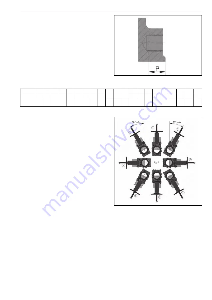
In horizontal pipes it is recommended that the knife gate
valves be assembled in vertical position, although other
assembly positions are also possible.
Fig. 3
Position 1:
This is the most advisable position.
Position 8:
The valve can be installed in this position but
you are advised to contact the supplier if this is necessary.
Positions 2, 3, 6 and 7:
For large valves (more than DN300),
the maximum angle with the installation vertical is 30º. For
smaller sizes the angle can be increased up to 90º (positions
4 and 5).
When it is necessary to install large valves in any of these
positions, it is recommended to consult the supplier, as in
these cases, due to the weight of the actuator, a suitable
support must be made to prevent deformations and
operating problems in the valves.
Positions 4 and 5:
For smaller sized valves, the valves can
be installed in these positions. To install larger valves (more
than DN300) in any of these positions, please contact the
supplier. In these cases, due to the weight of the actuator, a
suitable support must be made to prevent deformations
and operating problems in the valves.
DN
50
65
80
100 125 150 200 250 300 350 400 450 500 600 700 800 900 1000 1200 1300 1400
P
14
14
14
14
15
15
17
17
20
21
23
24
25
26
26
26
26
27
29
29
30
TORQUE
(Nm)
45
45
45
45
45
88
88
88
88
88
152 152 152 223 223 303 303
412
529
529
685


