IMO-R27
7
14. Gently place the body gasket (65) into the machined
recess of the body (1).
15. Apply a lubricant compatible with the tank car
commodity to the insert threads and screw the insert
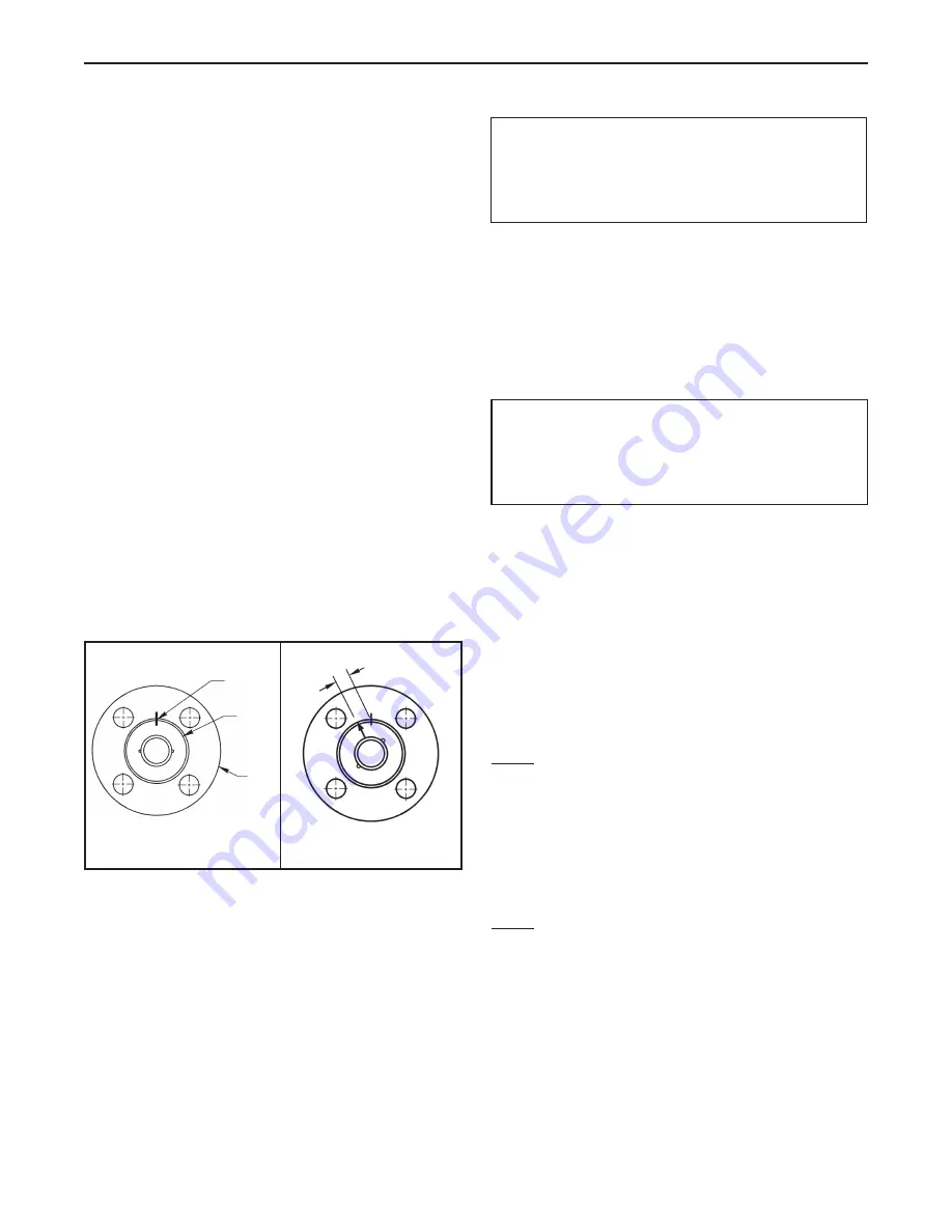
(2) into the body. The tightening of the insert should
be done using the insert field wrench. The insert must
be tightened the same number of turns as in Step 11,
insuring that the marks are no more than 1/8” (3.18
mm) apart, as shown in
Figure 7
.
16. Place the indicator stop (32) with “BTM” making facing
down, over the stem so that the longer part is over the
body.
17. Place the spring (33) over the stem (5) with the larger
diameter contacting the indicator stop (32).
18. Compress the spring (33) and hold down by putting
the retaining ring (34) in the groove in the stem (5).
19. If the valve is to be grounded, test as follows:
a. User an ohmmeter accurate to /- 10%
b. Check continuity between top of stem and body
base metal. Also check between ball and body base
metal. Precaution should be taken to prevent
scratching the ball OD.
c. Resistance in either the open, half open or closed
position shall not exceed 5 ohms using a source not
exceeding 12 volts.
20. With the ball in the open position, install handle (31)
and handle screw (35). NOTE: With the ball in the open
position the handle must be over the non-insert end of
the valve.
21. Cycle the valve slowly a few times to assure smooth
operation and to set the seats.
4.5 Pressure Testing the Valve
If the valve is to be tested prior to returning to service,
make sure the test pressures are in accordance with an
applicable standard.
When testing the valve for external tightness, keep the
ball in the half open position.
If testing the valve seat tightness, please contact Metso for
advice.
5 REPAIR KITS
Standard repair kits are listed in (
Table 1
). When ordering
repair kits for your valve refer to
Section 1.2, Valve
Markings
and check area “3” on your valve’s identification
plate determine the correct seat material for your valve.
6 SERVICE/SPARE PARTS
We recommend that valves be directed to our service
centers for maintenance. The service centers are equipped
to provide rapid turn-around at a reasonable cost and
offer new valve warranty with all reconditioned valves.
NOTE:
When sending goods to the service center for
repair, do not disassemble them. Clean the valve carefully
and flush the valve internals. Include the material safety
datasheet(s) (MSDS) for all media flowing through the
valve. Valves sent to the service center without MSDS
datasheet(s) will not be accepted.
For further information or assistance on repair kits and
spare parts, visit our website at
www.metso.com/valves
.
NOTE:
When ordering spare parts not included in repair
kits, always include the following information:
a. Valve catalog code from identification plate
b. If the valve is serialized, the serial number (stamped
on the valve body)
c. From
Figure 8
, the ballooned part number, part
name and quantity required.
WARNING:
WHEN PERFORMING ANY TESTS, NEVER EXCEED THE MAXIMUM
OPERATING PRESSURE OR MAXIMUM SHUT-OFF PRESSURE LISTED
ON THE IDENTIFICATION PLATE.
Figure 6
Figure 7
1/8
Mark
Position
Body
Insert
WARNING:
WHEN PRESSURE TESTING, EXERCISE CAUTION AND MAKE SURE ALL
EQUIPMENT USED IS IN GOOD WORKING CONDITION AND
APPROPRIATE FOR THE INTENDED PRESSURE.


