


4. Set the input signal at the closed limit of the valve so that it
is 2 % i.e. 0.02 bar (0.2 psig) higher or lower than the limit value,
e.g. 0.2 + 0.02 = 0.22 bar (3 + 0.2 = 3.2 psig) or 1.0 - 0.02 = 0.98 bar
(15 - 0.2 = 14.8 psig). Loosen the screw (56). Turn the zero
adjustment screw (67) so that the actuator comes slowly to the
closed limit. Tighten the screw (56) always after the zero
adjustment. The valve should open slightly with a 4 % change in
signal, that is 0.03 bar (0.5 psig), e.g. 0.2 + 0.03 = 0.23 bar (3 +
0.5 = 3.5 psig) or 1.0 - 0.03 = 0.97 bar (15 - 0.5 = 14.5 psig).
See Figure 11.
5. Set the input signal to the other limit value. The valve should be
entirely open at 100 %, i.e. 1.0 bar (15 psig) or 0.2 bar (3 psig). The
valve should start to operate to closed direction at 98 %, i.e. 0.98
bar (14.0 psig) or 0.22 bar (3.2 psig).
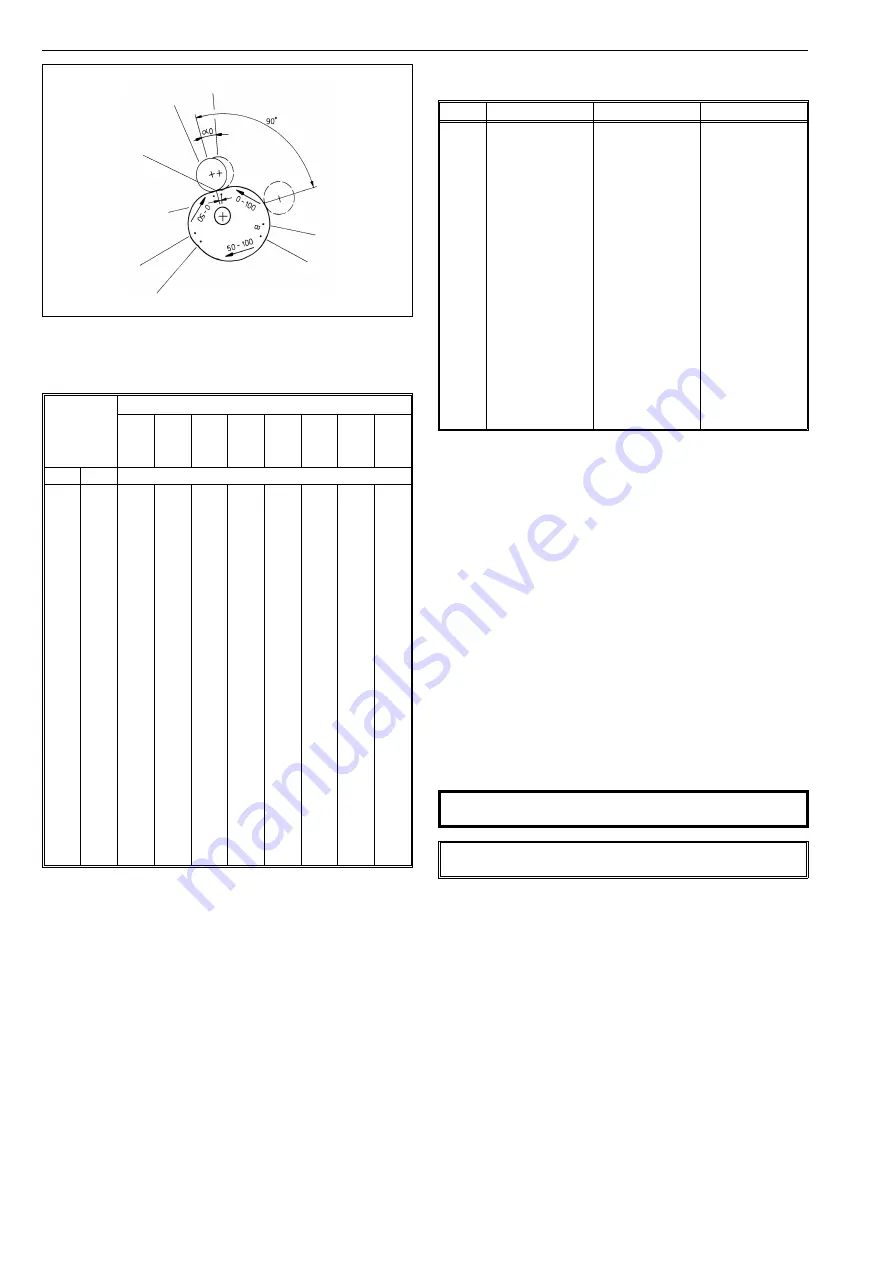
The range, i.e. turning angle, changes when the effective lenght
of the spring (60) is increased or decreased by turning the range
adjustment nut (60.3). See Fig. 11.
6. The zero and range adjustments affect each other, so stages 4
and 5 must be repeated a few times.
7. Screw on the pointer (32) into place so that the yellow line is in
the direction of the valve closing member. Tighten the screw (57).
7
SPLIT-RANGE ADJUSTMENT
In principle, split range adjustments are made in the same manner
as for a normal signal range. Select a split range, 0.2-0.6 bar (3-9 psig)
or 0.6-1 bar (9-15 psig), from the cam plate. See Figure 8.
8
MAINTENANCE
CAUTION:
Do not dismantle a pressurized positioner!
NOTE:
Ensure the cleanness of the air piping.
Regular maintenance is not necessary.
The need for maintenance depends on the quality of the instrument
air, see Section 2.5.
If there is need for servicing proceed according to the following
sections.
8.1
Supply air filter
The supply air filter (50) is located in the supply air connection (S),
the filter can be removed and cleaned with e.g. compressed air.
segment C
segment D
segment E
shift
Roller contact point when
the ball is completely closed
Fig. 13.
Shift on circumference of cam equal to dead angle
α
0
Segment C
Segment E
Segment D
20°
19°
18°
17°
16°
15°
14°
13°
12°
11°
10°
9°
8°
7°
6°
5°
4°
*)
*)
*)
*)
*)
3.1/0.12
2.9/0.11
2.7/0.10
2.5/0.09
2.3/0.09
2.1/0.08
1.9/0.07
1.7/0.06
1.5/0.05
1.3/0.05
1.1/0.04
0.9/0.03
6.1/0.24
5.8/0.22
5.5/0.21
5.2/0.20
4.9/0.19
4.6/0.18
4.3/0.16
4.0/0.15
3.7/0.14
3.4/0.13
3.1/0.12
2.8/0.11
2.5/0.09
2.2/0.08
1.9/0.07
1.6/0.06
1.3/0.05
8.1/0.31
7.7/0.30
7.3/0.28
6.9/0.27
6.5/0.25
6.1/0.24
5.7/0.22
5.3/0.20
4.9/0.19
4.5/0.17
4.1/0.16
3.7/0.14
3.3/0.12
2.9/0.11
2.5/0.09
2.1/0.08
1.7/0.06
*) Segment C:
α
0
max. 15°
Table 3.
Shift caused by dead angle, mm/inch
Valve size
Valve series
MBV
QMBV
1)
MBV
QMBV
2)
D
3)
T5,
QT5
QX-
T5
T25,
QT25
QX-
T25
R,
QR
mm
in
Dead angle in degrees
25
40
50
65
80
100
125
150
200
250
300
350
400
450
500
600
650
700
750
800
900
1
1
1
⁄
2
2
2
1
⁄
2
3
4
5
6
8
10
12
14
16
18
20
24
26
28
30
32
36
12.5
11.0
9.0
8.0
9.0
9.0
11.0
9.0
8.0
8.0
7.0
-
-
8.0
-
7.0
7.0
-
7.0
6.5
6.5
5.5
5.4
4.5
-
-
12.0
-
11.0
11.0
-
10.5
7.5
7.0
5.5
5.5
5.0
5.0
5.5
5.0
6.0
6.0
5.5
-
4.5
23.0
22.0
22.0
-
16.0
15.0
-
14.5
11.0
12.0
8.5
-
8.5(14")
7.0(16")
17.5
11.0
11.0
-
7.0
7.5
-
8.0
6.0
-
-
16.0
-
15.0
14.5
11.0
12.0
8.5
8.5
7.0
-
-
7.0
-
8.0
8.0
6.0
14
11
15
11
8
7
7
7
6
6
5
4
4
1)
Seat supported
2)
Trunnion
3)
S/G seat
Table 4.
Dead angle in degrees
10