SPLIT BOX FOR AIR-WATER HEATPUMP
MANUAL
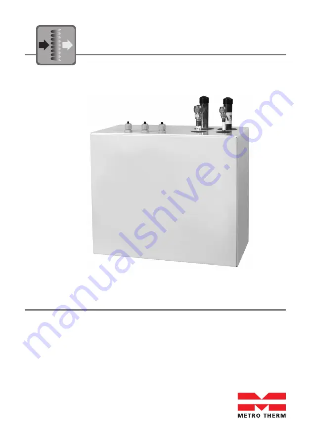
SPLIT BOX 6 kW
SPLIT BOX 8/12 kW
SPLIT BOX 16 kW
08:211-1805
Page 1: ...SPLIT BOX FOR AIR WATER HEATPUMP MANUAL SPLIT BOX 6 kW SPLIT BOX 8 12 kW SPLIT BOX 16 kW 08 211 1805...
Page 2: ...elivery 8 3 Positioning 9 4 Water Circuit 11 5 Refrigerant Circuit 12 6 Electrical Connections 12 7 Control and Operation 13 8 Maintenance 13 9 Disassembly and Decommissioning 13 10 Troubleshooting an...
Page 3: ...HBS 05 in terms of performance 1 1 Safety precautions The product shall be installed commissioned repaired only by qualified technicians Incorrect installation can result in damages of properties and...
Page 4: ...at allows safe working conditions The refrigerant can be toxic if inhaled or if in high concentrations Special attention should be given if the work is carried out with an open flame 1 3 Serial number...
Page 5: ...9 Signal cable to outdoor heat pump 10 Residual current device RCD optional 11 Cable for heat tracing optional A B D C 1 2 3 4 5 6 7 A Refrigerant flow B Refrigerant return C Space heating return D S...
Page 6: ...L53 Connection liquid line Valves etc EP2 Heat exchanger HQ1 Particle filter supplied HZ2 Drying filter Electrical components AA23 Communication board AA23 F3 Fuse for external heating cable AA23 S3 D...
Page 7: ...n the following figures and table 6 kW 8 12 kW 16 kW Dimensions LxBxH mm 460x250x400 Weight kg 16 18 23 Water connections compression fittings mm 22 28 28 Refrigerant hot gas inlet flow 1 2 5 8 5 8 Re...
Page 8: ...DELIVERY Immediately upon receipt the unit must be examined to make sure that it is intact and undamaged If not the shipping company must be informed immediately The recipient has the responsibility f...
Page 9: ...with existing floor drainage most suitably in a utility room or boiler room The bracket for the split box is mounted to the wall by use of appropriate screws Route pipes so they are not fixed to an in...
Page 10: ...12 Splitbox placering Min 200 mm Min 200 mm Min 300 mm Figure 8 Recommendation for positioning on wall 1 1 2 2 3 3 4 4 5 5 A B C D 990300013 Splitbox placering vinkel Min 400 mm Min 400 mm Figure 9 Re...
Page 11: ...valves on the water side XL1 and XL2 these must be installed to facilitate any future servicing When operating the split box free flow in the climate system is recommended for correct heat transfer T...
Page 12: ...the maximum pipe length maximum high differences pipe materials pipe diameters and other instructions as given in the installation manual for the outdoor unit Install test and commission the pipes be...
Page 13: ...regulations 10 TROUBLESHOOTING AND REPAIR The condenser and associated pipes and pipe components is fully casted into high efficient poly urethane foam to ensure excellent insulation and heat preserv...
Page 14: ...e XL53 Carefully cut away insulation material in the indicated squared box in front of the temperature sensor Remove the old sensor clean the pipe and make space to the replacement sensor Install the...
Page 15: ...ownloaded at www METROTHERM dk 12 PRODUCT AND INSTALLER INFORMATION Installed model Serial number Accessories Installers Pipe installation Date Company Name Phone number Electrical installation Date C...
Page 16: ...08 211 1805 METRO THERM A S RUNDINSVEJ 55 3200 HELSINGE INFO METROTHERM DK WWW METROTHERM DK...