background image

8

Seven (7) multi color LEDs (green, amber) located on the fuel gauge display the charging status of the power supply as 

described below:

CH AC LOW

R

Battery  Power

Fuel Gauge

Status

Battery is fully charged, all five right LEDs are illuminated.

CH AC LOW

R

Battery  Power

Battery is discharging under normal, mobile operation.

Example shown is about 50% charge remaining.

CH AC LOW

R

Battery  Power

Low battery LED flashing: plug power supply into AC

immediately.

CH AC LOW

R

Battery  Power

AC indicates the power supply is plugged into the wall AC.

CH indicates the battery is charging.

The amber LEDs will turn on in sequence to indicate the

charging status.

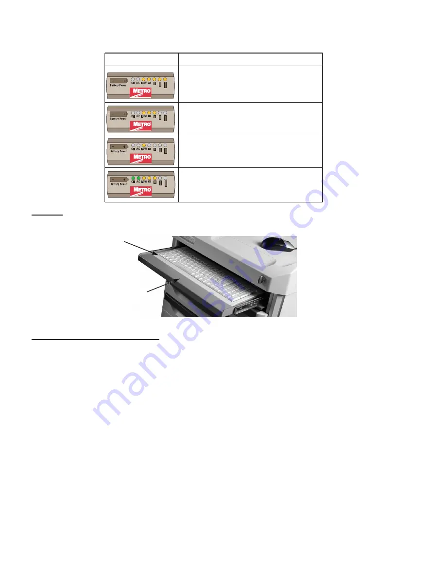
Keyboard

• 

A keyboard is situated underneath cart work surface and can be accessed by pulling out keyboard tray.  Keyboard 

is powered from power supply through USB hub.  The maximum size of keyboard the keyboard tray holds is 16”.

F

igure

 13:  k

eyboarD

All-In-One Computer/Monitor Mounting

• 

Depending on the accessory ordered, your monitor can be either mounted on the overbridge or on a post mounted 

articulating arm.

• 

When mounted on the overbridge, a monitor rail and monitor bracket are used.  The post mounted articulating arm 

is mounted at the left hand rear corner of cart.

•  Maximum load that overbridge can carry is 100lbs (45.4kg).

 ◦ Monitor rail can carry load upto 50lbs (22.7kg).

•  Minimum and maximum range of weight the articulating arm can carry is 6lbs (2.7kg) to 26lbs 

(11.7kg).

•  Vesa mounted plate is used to fix All-In-One computer on overbridge and articulating arm.
•  Overbridge is mounted at a single height of 17” (431.8mm) from the cart work surface as shown in Figure 12.
• 

Monitor rail can be mounted at any two consecutive holes on overbridge which make up the seven different 

mounting locations for All-In-One computer/monitors. Refer to Figure 12.

•  Powering Up the Monitor:

  The Starsys Cart power supply must be turned ON first before turning ON the monitor.  

The ON/OFF switch for monitor is located at the back of monitor and can be turned ON/OFF as required.

•  Adjusting the Display Position

:  To adjust the monitor position to tilt up or down, grab the top and bottom in each 

hand and move to the position desired.  To adjust the monitor position left or right, grab the sides with each hand 

and move to the position desired.

•  In order to avoid damaging the display’s screen, do not press the screen with your fingers.  A soft, clean, lint-free 

cloth or a lens brush of camel hair should be used to clean the screen.  Never pour or spray any type of liquid onto 

the display.  Additional information about the operation of the display can be found in the operating manual from the 

original manufacturer.

Keyboard

Keyboard Tray

Summary of Contents for STARSYS WIRELESS

Page 1: ...8705 For Product Information Call 1 800 992 1776 Visit Our Web Site www metro com INSTRUCTIONS FOR USE THIS MANUAL COVERS CARTS WITH ELECTRICAL RATINGS OF 12V 19V 24V STARSYS MOBILE POWER CART Metro Mobile Power Carts are for Health Care applications only L01 491 Rev A 10 2012 ...

Page 2: ...ng must be performed by qualified service personnel only For all service items please contact InterMetro Customer Service CAUTION Do not operate the Starsys cart if it has received a severe impact or has been otherwise physically damaged Please have a qualified service person inspect both the Starsys cart in conjunction with its power supply for any performance or safety hazard prior to putting ba...

Page 3: ...one computer monitor Internal external wire management protects cords from snags and damage Overbridge keeps supplies and equipment readily accessible Monitor rail and bracket are assembled to overbridge for mounting various All In One computer monitor For a greater range of movement Articulating Arm is installed on monitor pole The fuel gauge is mounted at the back top of cart which is used to mo...

Page 4: ...OT and IATA regulations Connecting the Power Supply Batteries CAUTION Only qualified service personnel should perform the following procedure for connecting the Power Supply Batteries 1 The AC cable must be disconnected from the wall outlet as shown in Figure 2 Figure 2 Disconnect AC Cable 2 The Normal Operation OFF switch of the Power Supply must be in the Standby down position as shown in Figure...

Page 5: ...el 6 Check that all connections have been made and properly seated with latches locked There are up to of 8 battery pack connectors in an Li Nano power supply as shown in Figure 7 Figure 7 Properly Seated Connections 7 Rotate the Battery Connector Access Panel back up pushing until the top is firmly seated against the case as shown in Figure 8 Re install the screws on sides of power supply that ho...

Page 6: ...F position The switch position disconnects the battery from any internal or external equipment and avoids deep discharges of the battery which can cause damage to the battery NOTE After the initial charge the charge time for a completely discharged battery is typically 4 hours NOTE If the Li Nano Power Supply has been switched to OFF for more than 1 week connect the cart to AC to wake up the power...

Page 7: ... to supply the equipment from the internal Li Nano rechargeable battery cells The power supply is designed for continuous operation and service is not interrupted by plugging in or unplugging the power supply Figure 10 Power Supply Lockalert Touchpad Touchpad See Figure 11 is powered by Li Nano battery supply separate charging for the touchpad is unnecessary Touchpad cable passes through the insid...

Page 8: ...ad that overbridge can carry is 100lbs 45 4kg Monitor rail can carry load upto 50lbs 22 7kg Minimum and maximum range of weight the articulating arm can carry is 6lbs 2 7kg to 26lbs 11 7kg Vesa mounted plate is used to fix All In One computer on overbridge and articulating arm Overbridge is mounted at a single height of 17 431 8mm from the cart work surface as shown in Figure 12 Monitor rail can b...

Page 9: ...nitor Mounted on Overbridge Figure 15 Monitor Mounted on Articulating Arm Articulating Arm Vesa Plate All In One Computer Monitor All In One Computer Monitor Overbridge Monitor Mounting Bracket Monitor Rail Wire Clip ...

Page 10: ...wer cord from AC power source before disassembly of power cord from power supply 1 Unplug power cord from power supply 2 Loosen and remove screw from clamp 3 Remove power cord from power supply 1 2 3 B 1 Transfer clamp to new power cord 2 Fix and tighten retained screw to clamp it to base of mobile power cart 3 Plug new power cord to power supply REFER TO SECTION Replacement Parts List FOR VARIOUS...

Page 11: ...d Apply 70 percent isopropyl alcohol to a clean nonabrasive cloth and then wipe the power supply enclosure Cleaners applied directly to the power supply enclosure could leak inside and cause damage Be careful not to splash solvents on power supply enclosure Disassembly of Power Supply from Cart WARNING Before disassembly power cord must be disconnected from the wall outlet NOTE Disconnect all wire...

Page 12: ...AC Coil Power Cord x 96 LG 2438mm RPSXRC13 657 UK AC Coil Power Cord x 96 LG 2438mm RPSXR403075 08 AU AC Coil Power Cord x 96 LG 2438mm RPSXRC13 658 SWISS AC Coil Power Cord x 96 LG 2438mm 11 RPC06 951 1 1 2 Dia 38mm Split Bushing 12 RPSXR92122 Ground Strap 13 RPSXRCONVR 12V Converter Assembly 12V Output RPSXRCONVR 19V Converter Assembly 19V Output RPSXRCONVR 24V Converter Assembly 24V Output 14 R...

Page 13: ...13 6 5 8 7 10 8 9 VIEW A VIEW B B A 4 2 3 1 2 15 16 42 60 60 60 24 24 11 42 10 2 17 11 18 Keyboard Tray Figure 17 Replacement Parts Sheet 1 of 2 ...

Page 14: ...14 1 EXPLODED VIEW OF POWER SUPPLY CABLES 2 5 14 13 12 10 4 8 7 6 10 36 96 To Computer 60 60 24 To Fuel Gauge To LA6 PCB 42 To Computer 3 60 19 Figure 18 Replacement Parts Sheet 2 of 2 ...

Page 15: ...15 WIRING DIAGRAM ...

Page 16: ...t connected during shipment due to USDOT AND IATA regulations Turn off computer equipment and then the power supply Make sure battery packs are connected by performing procedure in Section Connecting the Power Supply Batteries above Turn on the power supply and restart the computer equipment If this problem continues contact InterMetro Customer Service Power Supply Battery Pack Low Temperature Sys...

Reviews: