4
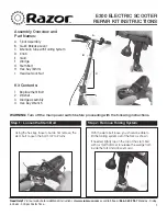
How to Set Up and Fold the Scooter
SETUP
The scooter is shipped in the compact storage position.
Follow the steps below to set up the scooter for use.
1. Push the button on the lock pin handle and pull the
lock pin out of the frame. Raise the upright until it is
in a nearly vertical position. Push the button on the
lock pin handle and reinsert the lock pin fully into
the frame.
2. Open the quick release lever. Press the push pin on
the stem of the handlebar and slide the stem up until
the push pin is visible in one of the three holes in the
upright. The handlebar should be at the height of the
user’s waist. Close the quick release lever so it is
tight against the upright.
Note: If the
quick release
doesn’t hold
the stem tight-
ly, the quick
release should
be adjusted.
Open the
quick release
lever. Turn the
adjustment nut clockwise one half turn while keeping
the lever from turning. Close the lever. Repeat this
procedure until the stem is held tightly.
If the quick release cannot be closed, turn the adjust-
ment nut counterclockwise one quarter turn while
keeping the lever from turning. Close the lever.
Repeat this procedure until the quick release closes
and the stem is held tightly.
Before using the scooter, make sure that the scooter is
set up as described and that all parts are securely
tightened.
The batteries must be charged before the scooter can
be used. Refer to page 5 for battery charging instruc-
tions.
FOLDING
When the scooter is not in use, it can be folded to the
storage position for compact storage or transport. Follow
the steps below to fold the scooter.
1. Make sure the on/off switch on the right side of the
scooter is in the off position with the key removed.
The on/off switch should always be in the off posi-
tion with the key removed when the scooter is not
in use.
2. Open the quick release lever. Press the push pin on
the stem and slide the stem into the upright. Close the
quick release lever.
3. Push the button on the lock pin handle and pull the
lock pin out of the frame. Pivot the upright down to
the horizontal position. Push the button on the lock
pin handle and reinsert the lock pin fully into the
frame.
Lock Pin
Lock Pin
Frame
Quick
Release
Lever
Upright
Upright
Push Pin
Stem
Nut
Open
Close
Lever
Quick
Release