Doc#
100576
• REV C
(Sept 2017) Page
38 of 42
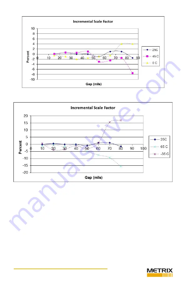
Figure 37: 7200 5m System ISF, 0 C to +45 C
Figure 38: 7200 5m System ISF, -35 C to +65 C
Page 1: ...r while the MX2034 is a two wire current loop transmitter Users can con figure either unit to measure peak to peak vibration gap distance or rotational speed These products are used in conjunction wit...
Page 2: ...vice Information 13 3 5 3 Device Communication Status 14 3 5 4 Configurable Device Settings 14 3 5 5 Confirming the Configuration 16 3 5 6 Printing a Label 16 3 5 7 Installing the Label 18 3 6 Using t...
Page 3: ...that may appear on the product and or in this manual include 1 2 GENERAL SAFETY SUMMARY Review the following safety precautions to avoid injury and prevent damage to this product or any products conne...
Page 4: ...conditions such as extreme temperature excessive humidity or a corrosive atmosphere 2 OVERVIEW The Metrix Digital Proximity System module comes in two versions MX2033 3 wire proximity driver MX2034 2...
Page 5: ...he MX2034 is powered by 24 Vdc supplied within the current loop The MX2034 is user configurable to function as either a radial vibration transmitter where the 4 20 mA signal is proportional to peak pe...
Page 6: ...he DPS configuration for measurement type MX2034 only Changing the DPS full scale range MX2034 only Printing DPS labels 3 1 EQUIPMENT REQUIRED You will need the equipment listed below to configure a D...
Page 7: ...rdering information Insert the USB stick into your computer and open explorer to view the files Double click the version for your operation system according to Table 2 and follow the instructions list...
Page 8: ...100576 REV C Sept 2017 Page 8 of 42 Figure 2 shows the end user license agreement Click Accept to continue Figure 2 License Agreement Figure 3 Installation Screen Click Install to begin the installat...
Page 9: ...resent a User Account Control notice as shown in Figure 4 Click Yes to continue Figure 4 Windows 7 User Account Control You may additionally see a Windows Security notice as shown in Figure 5 Click In...
Page 10: ...Doc 100576 REV C Sept 2017 Page 10 of 42 Click the Finish button as shown in Figure 6 to close the installation process Figure 6 Installation Complete Screen...
Page 11: ...computer 3 3 1 REMOVE THE BASE Remove the three screws from the DPS base to access the mini USB connector as shown in Figure 7 and Figure 8 Figure 7 Removing the Base Figure 8 The USB Plug Plug the US...
Page 12: ...or volt age and current requirements Powering is the same for either the MX2033 or the MX2034 The MX2034 does not require load resistors when configuring Figure 9 Powering the DPS 3 4 LAUNCHING THE DP...
Page 13: ...n as well as user specific information such as machine location etc Help Provide descriptions of the various features of the software 3 5 2 DEVICE INFORMATION The DPS software automatically retrieves...
Page 14: ...r Factory Calibration Date Date of the last time Metrix calibrated the device Last Configuration Change Date the configuration was last changed 3 5 3 DEVICE COMMUNICATION STATUS Table 3 Device Communi...
Page 15: ...four probe series listed in section 3 5 4 1 calibrated for 4140 steel The additional probe type specified at the time of ordering may be calibrated to a variety of materials Contact Metrix for informa...
Page 16: ...scale or downscale for the 4 20mA output of axial position measurements only Upscale means that for the range selected in 3 5 4 5 4mA corresponds to bottom of scale and 20mA corresponds to top of scal...
Page 17: ...ustom information click the OK button The label print start screen opens The label print start screen allows you to select the label position you want the label printing to start at This template is s...
Page 18: ...r 3 5 7 INSTALLING THE LABEL Remove the backing from the polycarbonate label and adhere the printed label inside the clear window Attach both labels to the side of the DPS unit Refer to DPS Label Kit...
Page 19: ...s the steps to verify proper DPS operation and to custom calibrate your DPS to your specific probe and cable CAUTION When using the MX2034 BNC connector exer cise special care to prevent ground loops...
Page 20: ...n fixed gap increments 4 1 1 1 OBTAINING THE TARGET Use a 1 2 inch or larger target with 5 mm or 8 mm probes Be sure your target material matches the material the DPS calibration material To verify th...
Page 21: ...cation requires these instruments and equipment Spindle micrometer Digital Multimeter Power Supply 24 Vdc 1Vdc 10 kohm resistor Figure 17 MX2033 Scale Factor Validation Set Up NOTE Use the BNC connect...
Page 22: ...TRICALLY ZERO THE PROBE Set the probe gap electrically to the start of the measurement range by observing the DC output voltage and adjusting the probe position until the output is 1 V 0 1 V at 10 mil...
Page 23: ...the voltage measured at 10 mils 0 25 mm from the voltage at 90 mils 2 25 mm and divide by the full scale range of 80 mils 2 mm Example Voltage at 90 mils 2 25 mm is 17 1 V Voltage at 10 mils 0 25 mm i...
Page 24: ...calibration window opens Enter the voltages measured at each gap from the Scale Factor Verification data When complete click the Generate and Load Linearization button The software will adjust the DPS...
Page 25: ...OK to finish Figure 21 Custom Calibration Successful Completion If the probe and cable run very far out of specification the DPS may not be able to linearize the curve In this case the software will...
Page 26: ...erating the custom calibration process several times 4 2 1 CURRENT LOOP VERIFICATION MX2034 ONLY Follow the steps in this section to verify the current loop output for Position or Radial Vibra tion co...
Page 27: ...IG Voltage from the volt meter and the current output measured by the Ammeter mils mm SIG Voltage Current 10 0 25 20 0 50 30 0 75 40 1 00 50 1 25 60 1 50 70 1 75 80 2 00 90 2 25 Use the following equa...
Page 28: ...N The transmitter current output is linearly proportional to the full scale vibration range between 4 mA and 20 mA The following equation represents the relationship between the vibration and the loop...
Page 29: ...a sure between SIG and COM at the DPS to verify the SIG out voltage If SIG out is correct the field wir ing is shorted or disconnected at the monitor side Scale Factor is high Cable length or probe se...
Page 30: ...w Verify that total loop resis tance does not exceed the maximum per Installation Manual 100545 Current output stuck 3 5 mA Probe is disconnected or out of range Verify that the probe is con nected an...
Page 31: ...FORMANCE GRAPHS 6 1 DRIVER TRANSMITTER TEMPERATURE RESPONSE Shown with custom calibration and represent typical performance over temperature DPS unit only at temperature 6 1 1 MX2030 BN 3300 5 METER S...
Page 32: ...Doc 100576 REV C Sept 2017 Page 32 of 42 Figure 25 MX2030 5m System DSL 0 C to 45 C Figure 26 MX2030 5m System DSL 35C to 65 C...
Page 33: ...Doc 100576 REV C Sept 2017 Page 33 of 42 Figure 27 MX2030 5m System ISF 0 C to 45 C Figure 28 MX2030 5m System ISF 35 C to 65 C...
Page 34: ...Doc 100576 REV C Sept 2017 Page 34 of 42 6 1 2 MX2030 BN 3300 9 METER SYSTEM Figure 29 MX2030 9m System 35 C to 65 C Figure 30 MX2030 9m System DSL 0 C to 45 C...
Page 35: ...Doc 100576 REV C Sept 2017 Page 35 of 42 Figure 31 MX2030 9m System DSL 35 C to 65 C Figure 32 Mx2030 9m System ISF 0 C to 45 C...
Page 36: ...Doc 100576 REV C Sept 2017 Page 36 of 42 Figure 33 MX2030 9m System ISF 35 C to 65 C 6 1 3 METRIX BN 7200 5 METER SYSTEM Figure 34 7200 5m System 35 C to 65 C...
Page 37: ...Doc 100576 REV C Sept 2017 Page 37 of 42 Figure 35 7200 5m System DSL 0 C to 45 C Figure 36 7200 5m System DSL 35 C to 65 C...
Page 38: ...Doc 100576 REV C Sept 2017 Page 38 of 42 Figure 37 7200 5m System ISF 0 C to 45 C Figure 38 7200 5m System ISF 35 C to 65 C...
Page 39: ...Doc 100576 REV C Sept 2017 Page 39 of 42 6 1 4 METRIX BN 7200 9 METER SYSTEM Figure 39 7200 9m System 35 C to 65 C Figure 40 7200 9m System DSL 0 C to 45 C...
Page 40: ...Doc 100576 REV C Sept 2017 Page 40 of 42 Figure 41 7200 9m System DSL 35 C to 65 C Figure 42 7200 9m System ISF 0 C to 45 C...
Page 41: ...76 REV C Sept 2017 Page 41 of 42 Figure 43 7200 9m System ISF 35 C to 65 C 6 2 PHASE DELAY Figure 44 shows the expected phase shift error as the measured frequency increases Figure 44 Phase Delay vs F...
Page 42: ...e General Electric Company in the United States and other countries Microsoft Excel Windows and Outlook and their respective designs are marks of Microsoft Corporation in the United States and other c...