background image

3

99-9011

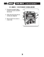
DASH DISASSEMBLY

Remove (4) T-20 Torx screws to
remove radio.

3

Disconnect the negative battery 
terminal to prevent an accidental
short circuit.

1

Unclip and remove trim panel sur-
rounding radio. 

(Figure A)

2

PASSE

NGER A

IR BAG

OFF

ON

VOL

SCAN

TUNE

BASS

TREB

BAL

FAD

FM

AM

CD

AC

FM2

103.7MHZ

72

64

80

1

2 3

4

CC 2009 / VW PASSAT 2006-2009

A

Summary of Contents for 99-9011

Page 1: ...using B ISO Brackets C ISO Trim Plate D DDIN Brackets E DDIN Trim Plate F Pocket KIT COMPONENTS 99 9011 A B VW CC 2009 EOS 2007 09 New Jetta 2005 09 GLI 2008 09 GTI 2006 09 Passat 2006 09 Rabbit 2006...

Page 2: ...sion with Pocket 6 ISO Head Unit Provision with Pocket 7 Double DIN Head Unit Provision 8 Stacked ISO Head Unit Provision 9 Final Assembly 10 KNOWLEDGE IS POWER Enhance your installation and fabricati...

Page 3: ...remove the grille from the top center of dash Figure A 2 Remove one T 20 torx screw from black insert from under grille removed in step one Figure B 3 Remove insert Figure C 4 Remove two T 20 torx sc...

Page 4: ...embly above the radio Figure E 6 Remove two T 20 torx screws from top sides of radio climate panel Figure F 7 Remove four T 20 torx screws to remove the radio Figure H 9 Remove panel Figure G 8 NEW JE...

Page 5: ...Disconnect the negative battery terminal to prevent an accidental short circuit 1 Unclip and remove trim panel sur rounding radio Figure A 2 PASSENGER AIR BAG OFF ON VOL SCAN TUNE BASS TREB BAL FAD F...

Page 6: ...remove passenger air bag light panel to the right of the hazard light button Figure A 2 Remove 2 T 20 Torx screws exposed behind the two panels removed in the two previous steps Figure B 4 Unclip and...

Page 7: ...A B EOS 2007 2009 Disconnect the negative battery terminal to prevent an accidental short circuit 1 Unclip and remove the radio trim panel Figure A 2 Remove the 4 screws securing the radio Unplug and...

Page 8: ...the radio hous ing Figure C 3 Slide the DIN cage into the Radio Housing and secure by bending the metal locking tabs down Figure A 1 Slide the aftermarket head unit into the cage and secure Figure B...

Page 9: ...Slide the head unit into the radio opening until the side clips engage Figure B 2 Snap the ISO Trim Plate into the Radio Housing Figure C 3 ISO HEAD UNIT PROVISION WITH POCKET A B C Mount the ISO Bra...

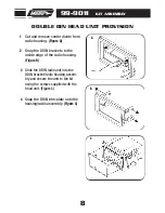
Page 10: ...unit to the kit using the screws supplied with the head unit Figure C 3 Cut and remove center divide from radio housing Figure A 1 Snap the DDIN trim plate onto the housing radio assembly Figure C 4...

Page 11: ...to the inside edge of the radio housing Figure B 2 Slide the stacked ISO DIN units into the DDIN bracket radio housing assembly and secure the units to the kit using the screws supplied with the head...

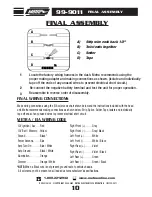
Page 12: ...ack Right Rear Violet Right Rear Violet Black Left Rear Green Left Rear Green Black METRA EIA WIRING CODE NOTE When a Black wire is not present ground radio to vehicle chassis All colors may not be pr...

Reviews: