


7.
Troubleshooting
In case of malfunction, review the following list and check if it is possible to put the ap-
pliance in order without a service call. In all enquiries, please contact the nearest Metos-
service.
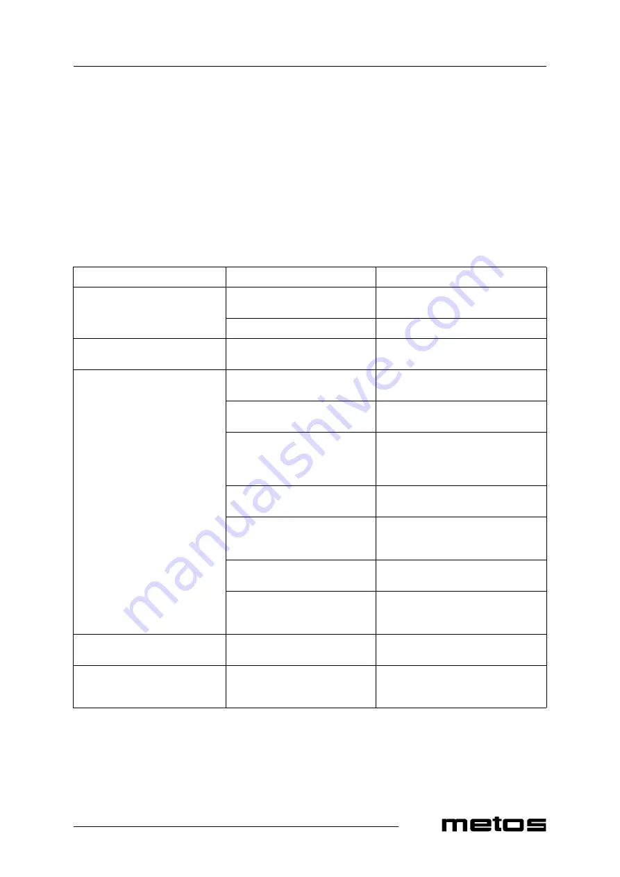
PROBLEM
POSSIBLE CAUSE
ACTION
The appliance does not start even if
the main switch is turned on (indica-
tor light is not lit)
Electrical cable is not properly
plugged into the socket.
Set the cable properly
Fuse has blown
Change the fuse
The main switch is working normal-
ly, but the fan does not start
The door is open or the door switch is
damaged
Close the door and check that the door
switch can move freely
The compressor is running but the
temperature does not fall to the set
value. The product temperature does
not fall within the normal chilling
time.
Condenser is covered by dust
Clean the condenser according to instruc-
tions
Prevented air circulation beside the
condenser
Ensure appropriate air circulation. Check
the cabinet surroundings.
Ambient temperature is too high
Make sure that the appliance has not been
placed near a heat source. Move the cabi-
net to a cooler place and arrange ventila-
tion if necessary.
Door switch does not work
Make sure that the door switch can move
freely.
Evaporator is covered by ice
Start manual defrost. If the appliance does
not work normally after the defrost cycle,
contact service personnel.
Cabinet is overloaded or product
thickness is too great
Reduce the amount of products and/or re-
arrange them
Products have been placed so that
they hinder air circulation inside the
cabinet
Arrange the products so that air circulation
is free
While running, the cabinet makes ex-
ceptionally loud noise
The cabinet is not firmly in place
Position the cabinet with adjustable legs
horizontally so that all legs touch the floor
The cabinet’s internal temperature is
higher than normal, the compressor is
not running
Defrost in operation: LED (5) is on,
“d” is shown on the display
Wait until the defrost cycle is complete.
Check the temperature after that.
Summary of Contents for SF 500
Page 2: ......
Page 4: ...13 2 2009 Rev...
Page 16: ...13 2 2009 Rev 4 0 Troubleshooting11 12...
Page 18: ...Refrigeration circuit diagram...
Page 22: ...13 2 2009 Rev 4 0 Technical specifications 18 Installation drawing 500 J G...
Page 23: ...13 2 2009 Rev 4 0 Technical specifications 19 Installation drawing 700 G J...
Page 25: ......