background image

15

OPERATION MANUAL

4. OPERATION

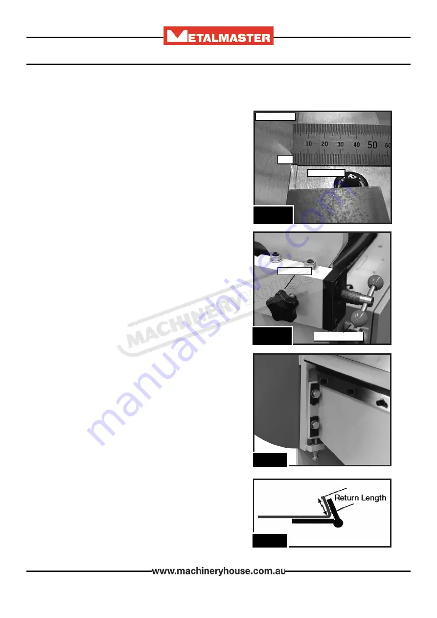
4.1 SETTING THE CLAMP GAP

Before operating the machine the clamp gap needs 

be set to match the material thickness

The Clamp gap must be set to a minimum of 1.5 x

material thickness. (Fig. 4.1)

Example: If the material that is to be bent is 2mm

then the clamp gap must be set to a minimum of

3mm.

Each panbrake may have different mechanisms for

adjusting the clamp gap but the formula of 1.5 x

Material Thickness must be maintained to prevent

overload and possible damage.

These machines are fitted with an easy to use clamp 

beam adjustment. There are two adjustment screws 

(Fig.4.2)  on the machine situated on each side of 

the machine. 

To adjust

1.   Loosen the lock screws on both sides

2.   Turn the two adjusting screws until the gap    


(Fig.4.2)  is correct.

3.   Tighten the two lock screws and recheck the gap

If needed, a combination of top clamp adjustment 

and apron adjustment can be applied. 


NOTE:

 The locking bolts on the apron must be re-

leased before adjusting, then tightened when the 

correct height is reached.

RETURN LENGTH - LIMITATION 


Caution

 - There is a minimum “Return Length” of 15 

x Thickness of Material when bending thicker mate-

rial over 1mm. Damage could occur to the machine 

if the return is too short.

Example:  If bending 2mm the minimum return 

length must be 30mm (Fig. 4.4) 

F

ig

. 4.1

C

lamp


Finger

F

olding


arm

g

ap

F

ig

. 4.2

l

oCk


sCrew

a

djusting


sCrew

F

ig

. 4.3

F

ig

. 4.4

22/07/2019

Instructions Manual for PB-422L (S576)

15

Summary of Contents for PB-422L

Page 1: ...HYDRAULIC NC PANBRAKE OPERATION MANUAL Edition No PB 422 820 1 Date of Issue 07 2019 Models PB 422L PB 820L Order Code S576 Order Code S583 22 07 2019 Instructions Manual for PB 422L S576 1 ...

Page 2: ...ERIAL NO DATE OF MANF Note This manual is only for your reference Owing to the continuous improvement of these Metalmaster machine changes may be made at any time without obligation or notice Please ensure the local voltage is the same as listed on the specification plate before operating any electric machine Distributed by www machineryhouse co nz MACHINE DETAILS 22 07 2019 Instructions Manual fo...

Page 3: ...3 Machine Leveling 12 3 4 Electrical Installation 13 3 5 Full Load Current 13 3 6 Attaching the Accessories 14 3 7 Filling The Oil Tank 14 4 OPERATION 4 1 Setting The Clap Gap 15 4 2 Operating Controls 16 4 3 Controller Operation 17 4 4 Start Up 19 4 5 Bending 19 5 MAINTENANCE 5 1 Type and frequency of Inspections 19 5 2 Changing The Hydraulic Oil 20 5 3 Changing The Hydraulic Oil Filter 20 5 4 Tr...

Page 4: ...W hp 2 2 3 2 2 3 Voltage V 240 240 Amperage A 15 15 Dimensions L x W x H cm 170 x 180 x 130 290 x 180 x 130 Shipping Dimensions L x W x H cm 190 x 80 x 145 300 x 80 x 145 Nett Weight kg 1100 1600 1 2 ACCESSORIES r Roving Foot Pedal With Control Panel r Adjustable Rear Manual Backgauge r Hydraulic Oil r Manual NOTE The above specifications were current at the time this manual was published but be c...

Page 5: ... 3 IDENTIFICATION 1 2 3 4 6 7 8 5 1 Clamping Beam 5 Mobile Foot Control 2 Folding Apron 6 Electrical Cabinet 3 Box Fingers 7 Angle Table 4 Clamping Ram 8 Hydraulic Oil Tank 22 07 2019 Instructions Manual for PB 422L S576 5 ...

Page 6: ...turer will not be held liable for injury or property damage from negligence improper training machine modifications or misuse WARNING 2 1 GENERAL METALWORKING MACHINE SAFE PRACTICES Always wear safety glasses or goggles Wear appropriate safety footwear Wear respiratory protection where required Gloves should never be worn while operating the machine and only worn when handling the work piece Wear ...

Page 7: ...hines and the surrounding area when the operation is finished Use proper lock out procedures when servicing or cleaning the machines or power tools Do not distract an operator Horseplay can lead to injuries and should be strictly prohibited Do not wear loose clothing gloves necktie s rings bracelets or other jewellery that can be come entangled in moving parts Confine long hair Do not handle cutti...

Page 8: ...mination and waste Soft tissue injuries for example to the hands arms shoulders back or neck resulting from repetitive motion awkward posture extended lifting and pressure grip Other Hazards Slips and falls from and around machinery during maintenance Unstable equipment that is not secured against falling over Safe access to from machines access egress Fire or explosion Pressure injection injuries...

Page 9: ... people in the area Ensure the area is clear before using equipment OPERATIONAL SAFETY CHECKS Remove the pan brake fingers that are in the way Use only the pan brake fingers required to make the bend Ensure the pan brake fingers that are not removed for an operation are securely seated and firmly tightened before the machine is used Ensure your fingers and limbs are clear before operating the pan ...

Page 10: ...he loads that apply When the slings are at a 45 angle then each sling is carrying the equivalent of 50 of load weight Fig 2 1 When the slings are at a 90 angle then each sling will have a weight equal to 75 of the load on each sling Fig 2 2 Note The manufacturer recommends not to exceed 90 angle Fig 2 2 Fig 2 1 When lifting the machine only certified lifting slings should be used Ensure that when ...

Page 11: ...essed through the machine and provide enough space around the machine for operat ing the machine safely Consideration should be given to the installation of auxiliary equip ment Leave enough space around the machine to open or remove doors covers as required for the maintenance and service as described in this manual It is recommended that the machine is anchored to the floor to prevent tipping or...

Page 12: ...of the base of the machine and the jacking screw adjusted until level Once level then tighten the hold down bolts Fig 3 3 The machine must not rest on supports other than those defined in Fig 3 3 Fig 3 2 In some case a suitable foundation may not be available and a new one may need to be prepared The foundation should be concrete approximately 200mm thick with pockets left clear for the hold down ...

Page 13: ...ting is the amperage a machine draws at when running at 100 of the output power Where machines have more than one motor the full load current is the amperage drawn by the largest motor or a total of all the motors and electrical devices that might operate at one time during normal operations Full Load Current Rating for these machine at 240V is 12 8 Amps It should be noted that the full load curre...

Page 14: ...plug Fig 3 5 q Install the manual back gauge making sure that the packing blocks are in place to raise the back gauge to the correct height Fig 3 6 3 7 FILL THE HYDRAULIC OIL TANK To fill the tank with oil 1 Remove the oil tank cover 2 Make sure the inside of the tank is clean and clear of any dirt 3 Using a pump fill the tank with oil until the level reaches the centre mark of the oil indicator O...

Page 15: ...hine situated on each side of the machine To adjust 1 Loosen the lock screws on both sides 2 Turn the two adjusting screws until the gap Fig 4 2 is correct 3 Tighten the two lock screws and recheck the gap If needed a combination of top clamp adjustment and apron adjustment can be applied NOTE The locking bolts on the apron must be re leased before adjusting then tightened when the correct height ...

Page 16: ...at the Apron is stationary at the end of the bend before returning 5 Manual Auto Switch Selects between either manual of automatic operation 6 Inch Down When pressed lowers the apron when in Manual mode 7 Auto Start Once Auto 5 is selected then when pressed completes one cycle 8 Bend Up When in Manual mode raises the apron when pressed 9 Pump Stop Stops the hydraulic pump 10 Pump Start Starts the ...

Page 17: ...ror bending and then recorded elsewhere for future use Value Angle relationships will also change depending on type and thickness of material being bent Press the blue right hand pointing arrow The S Value column of the display will start flashing Each time you press this arrow it will move the flashing digit across to the next one When you reach the digit you want to change then stop Then press t...

Page 18: ...the bending beam will come up until it is released at required bend angle Check angle and re bend further if needed q Press BENDING DOWN to lower bending beam AUTOMATIC BENDING q Ensure emergency stop button is released q Start hydraulic pump q Set Bending angle on BENDING ANGLE Display S Value to the required Value See SETTING BENDING ANGLE VALUE please note the set value is not the angle in degr...

Page 19: ...f inching or cycle mode can be selected d Do not bend material which has been welded or deformed Inspection Frequency Responsible Lubrication of all grease points Daily Operator Lubrication of clamp fingers and machine surfaces Daily Operator Guards for physical damage Daily Operator Machine fixing bolts against loosening Weekly Operator Oil Leakage in cylinders Weekly Operator Oil leakages in hos...

Page 20: ...ter every 1000 working hours 5 2 CHANGING THE HYDRAULIC OIL FILTER From time to time the hydraulic oil filter may need to be changed to ensure the quality of the system Filters used by the manufacture may change from model to model but basic procedure is listed below To change the oil 1 Remove the 4 socket head cap screws holding the tank cover and remove the oil tank cover Fig 5 1 2 Using an appr...

Page 21: ... valve Clean valve Change valve Clean filter Check pump and change if necessary Find the leaks and repair Press reset button Apron does not operate Low pressure in lifting cylinders Leakage in lifting cylinders Check system pressure Replace piston seal Oil leaking from cylinder Gland seal is damaged Change seal Oil leaking from fittings Loose fittings Tighten fittings If the machine develops a pro...

Page 22: ... time without notification HOW TO ORDER SPARE PARTS 1 Have your machines model number serial number date of manufacture on hand these can be found on the specification plate mounted on the machine 2 A scanned copy of your parts list diagram with required spare part s identified 3 Go to www machineryhouse com au contactus and fill out the enquiry form attaching a copy of scanned parts list 22 07 20...

Page 23: ...23 OPERATION MANUAL ELECTRICAL DIAGRAM 22 07 2019 Instructions Manual for PB 422L S576 23 ...

Page 24: ...24 OPERATION MANUAL HYDRAULIC DIAGRAM 22 07 2019 Instructions Manual for PB 422L S576 24 ...

Page 25: ...re connecting 14 Use correct amperage extension cords Undersized extension cords overheat and lose power Replace extension cords if they become damaged 15 Keep machine well maintained Keep blades sharp and clean for best and safest performance Follow instructions when lubricating and changing accessories 16 Keep machine well guarded Make sure guards on machine are in place and are all working corr...

Page 26: ...ork area hazards Keep the area around the Panbrake clean from oil tools objects chips Pay attention to other persons in the area and know what is going on around the area to ensure unintended accidents Do not access the rear of machine while the machine is working 10 Guards Operate machine only with all protective devices and guarding 11 Overloading Panbrake Do not exceed the rated capacity of the...

Page 27: ...trategies Recommended for Purchase Buyer User Keep hands clear of folder blades when clamping Secure support work material Body parts should be kept clear of moving parts Care must be taken when handling folder blades MEDIUM Machine should be installed checked by a Licensed Electrician Wear safety glasses Keep clear of bending material Ensure blade fingers are secured to clamp beam OTHER HAZARDS N...

Reviews: